Harvested crop processing unit with number of circulation circuits depending on throughput

a technology of circulation circuits and processing units, applied in the field of agricultural combines, can solve the problems of large corn loss to the harvesting process, high cost of technical and operator errors, etc., and achieve the effect of avoiding harvest crop losses, reducing labor intensity, and reducing labor intensity

Inactive Publication Date: 2009-01-08
DEERE & CO
View PDF28 Cites 15 Cited by
  • Summary
  • Abstract
  • Description
  • Claims
  • Application Information

AI Technical Summary

Benefits of technology

[0008]In this way the result is that the harvested crop is conveyed to the rear alternately by the guide rails of the first group and the guide rails of the second group in the case of a volume throughput below a threshold volume, since it is delivered to the leading end of the guide rails of the second group by the trailing end of the guide rails of the first group (after a circuit of the underside of the rotor). Since the leading ends of the guide rails of the second group are located ahead of the leading ends of the guide rails of the first group in the direction of rotation of the rotor the guide rails of the second group include one part of the harvested crop reaching the guide rails of the first group at smaller volume throughput values at volume throughput values above the threshold values, so that this part of the harvested crop then does not interact with the guide rails of the first group and therefore performs a smaller number of circuits of the rotor housing (in comparison to volume throughput values below the threshold value). The threshold value is determined by the axial distance between the leading ends of the guide rails of the first group and the leading end of guide rails of the second group. In other words, the flow of harvested crop spreads out with increasing volume throughput values and the guide rails of the second group receive a part of it upon exceeding the threshold value and that part reaches the outlet faster, since this part interacts only with the guide rails of the second group but not the guide rails of the first group.
[0009]Thereby the result is that volume throughput values below the threshold perform predetermined number of circuits through the harvested crop processing unit. At greater volume throughput values the guide rails of the second group convey a part of the harvested crop with a smaller number of circuits and therefore at a higher axial velocity to the output of the harvested crop processing unit. Thereby an overload of the rotor housing with harvested crop or with straw is avoided and an appropriate separating performance is attained as well as losses of harvested crop avoided. A repositioning of the guide rails or a determination of the actual throughput values is not required.

Problems solved by technology

If less than the predetermined volume throughput runs through the separating rotor or the separating section, the harvested crop can run through the separating rotor or the separating section faster than desired to the end of the separating rotor or the separating section, and a large proportion of corn is lost to the harvesting process.
Both of these possibilities are costly technically and subject to operator error.

Method used


Image

  • Harvested crop processing unit with number of circulation circuits depending on throughput
  • Harvested crop processing unit with number of circulation circuits depending on throughput
  • Harvested crop processing unit with number of circulation circuits depending on throughput

Examples


Embodiment Construction

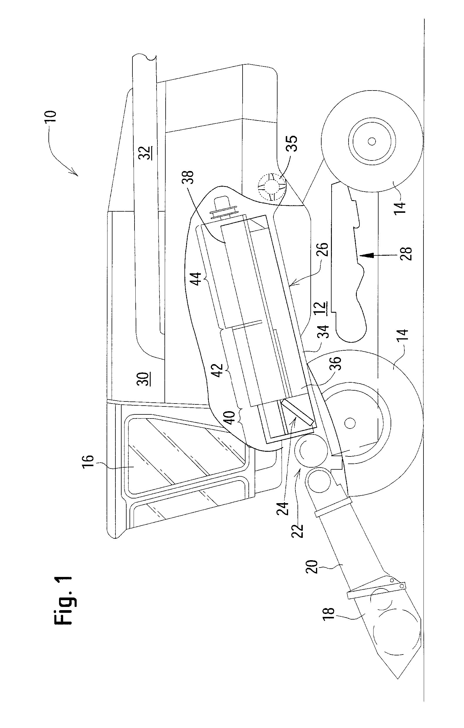
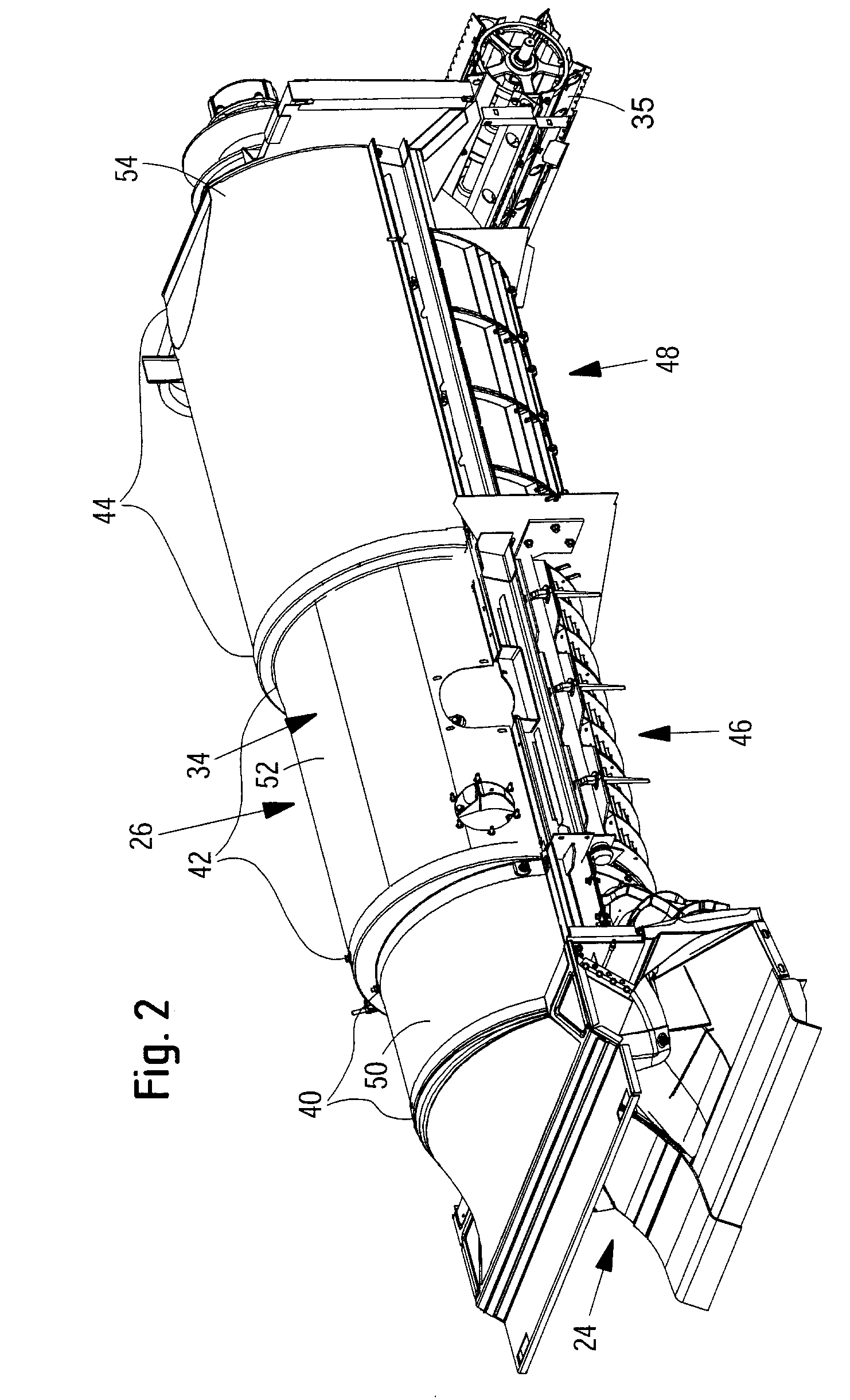
[0021]Referring now to the drawings, and more particularly to FIG. 1, there is shown an agricultural combine 10 with a supporting structure 12 with wheels 14 in contact with the ground that are fastened to the structure 12. The operation of the combine 10 is controlled from an operator's cab 16. A cutter head 18 is used to cut harvested crop containing corn and to conduct it to a slope conveyor 20. The harvested crop is conducted by the slope conveyor 20 to a guide drum 22. The guide drum 22 guides the harvested crop through an inlet transition section 24 to an axial harvested crop processing unit 26.

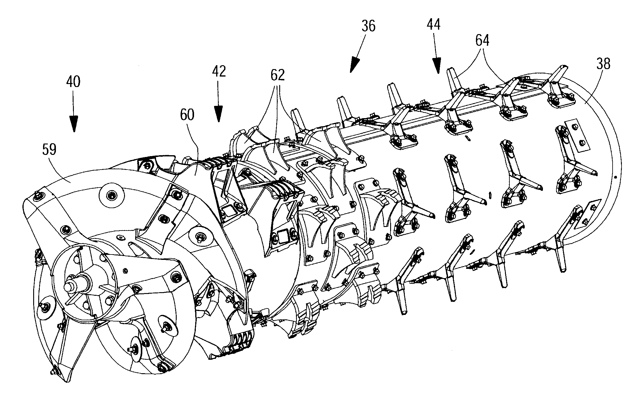
[0022]The harvested crop processing unit 26 includes a rotor housing 34 and a rotor 36 arranged within it. The rotor 36 includes a hollow drum 38 to which harvested crop processing elements are fastened for a charging section 40, a threshing section 42 and a separating section 44. The charging section 40 is arranged on the forward side of the axial harvested crop processing unit 26. The...


PUM


Abstract

A harvested crop processing unit with a rotor and a rotor housing enclosing the rotor, that includes a cover element under which a first group of helically shaped guide rails and a second group of helically shaped guide rails are attached, where the guide rails of the two groups follow each other alternately and are provided with a leading end and a trailing end in the direction of rotation of the rotor and the guide rails of the first group are arranged offset to the rear of the guide rails of the second group in the direction of rotation of the rotor. The trailing ends of the guide rail of the first group are directed at the leading end of the guide rails of the second group following in the axial direction of the rotor housing.

Description

FIELD OF THE INVENTION[0001]The present invention relates to agricultural combines, and, more particularly, to harvested crop processing units.BACKGROUND OF THE INVENTION[0002]Agricultural combines are large machines that harvest, thresh, separate and clean the agriculturally planted harvested crop which carries corn. The clean corn obtained in this way is stored in a corn tank on the combine. Rotary combines use one or two rotors enclosed in a rotor housing as a harvested crop processing arrangement to thresh and separate the harvested crop. The rotors are provided with a charging section that accepts harvested crop that had been harvested from the field, a threshing section to thresh the harvested crop received from the charging section and a separating section to release the corn that is still contained in the harvested crop after the threshing in the threshing section. During the rotation of the rotor the harvested crop is moved in the longitudinal direction from the charging se...

Claims


Application Information

Patent Timeline
Patent Type & Authority Applications(United States)
IPC IPC(8): A01F12/00
CPCA01F7/067
Inventor BECKER, KLAUSBUERMANN, MARTINBRAUNHARDT, KLAUSPIRRO, PETER
Owner DEERE & CO
Why Eureka
Try Eureka