Locking differential including disengagement retaining means

a technology of locking differential and disengagement retaining means, which is applied in the direction of fluid couplings, gearing, slip couplings, etc., can solve the problems of differential failure, tooth wear, clutch teeth chattering during engagement and disengagement, etc., and achieve the effect of preventing relative axial displacement of friction rings and preventing rotational movemen

Inactive Publication Date: 2009-01-08
EATON CORP
View PDF9 Cites 26 Cited by
  • Summary
  • Abstract
  • Description
  • Claims
  • Application Information

AI Technical Summary

Benefits of technology

[0008]According to a more specific object of the invention, the cam means includes a cam arm that is fixed at one end to one of the clutch members, said cam arm containing at its other end a generally T-shaped recess for receiving a cam follower pin that extends radially outwardly from the other clutch member, thereby to positively retain the overrunning clutch in the disengaged condition. In this embodiment, the friction drag means comprises a pair of resilient split friction rings that are respectively arranged concentrically between annular spacer members pinned to the side gears, and the inner circumferential surfaces of counterbores contained in the remote ends of the clutch members. Friction ring pins prevent rotational movement of the friction rings relative to their associated spacer members, and integral annular ribs on the friction rings cooperate with corresponding grooves contained in the clutch members, thereby to prevent relative axial displacement of the friction rings.
[0009]According to another object of the invention, the retaining means comprises a pair of holdout rings that connected for angular displacement relative to the clutch members, which holdout rings have radially outwardly flange portions that carry a plurality of axially extending lugs adjacent the side gears, such that when one of the clutch members is in the disengaged condition upon the overrunning of the associated output shaft, the associated holdout ring is slightly angularly displaced so that the lugs engages the tips of the teeth of the side gears, thereby to positively retain the clutch member associated with the overrunning shaft in the disengaged condition. In this embodiment, the friction drag effect is provided by resiliently outwardly biased segments of the body portion of each holdout ring.

Problems solved by technology

One drawback of the known differentials is the chattering of the clutch teeth during the engagement and disengagement that occurs when a clutch member is disengaged from the associated side gear.
This results in tooth wear at the tips of the clutch teeth on the clutch and side gear members, which could possibly result in the failure of the differential.

Method used


Image

  • Locking differential including disengagement retaining means
  • Locking differential including disengagement retaining means
  • Locking differential including disengagement retaining means

Examples


Embodiment Construction

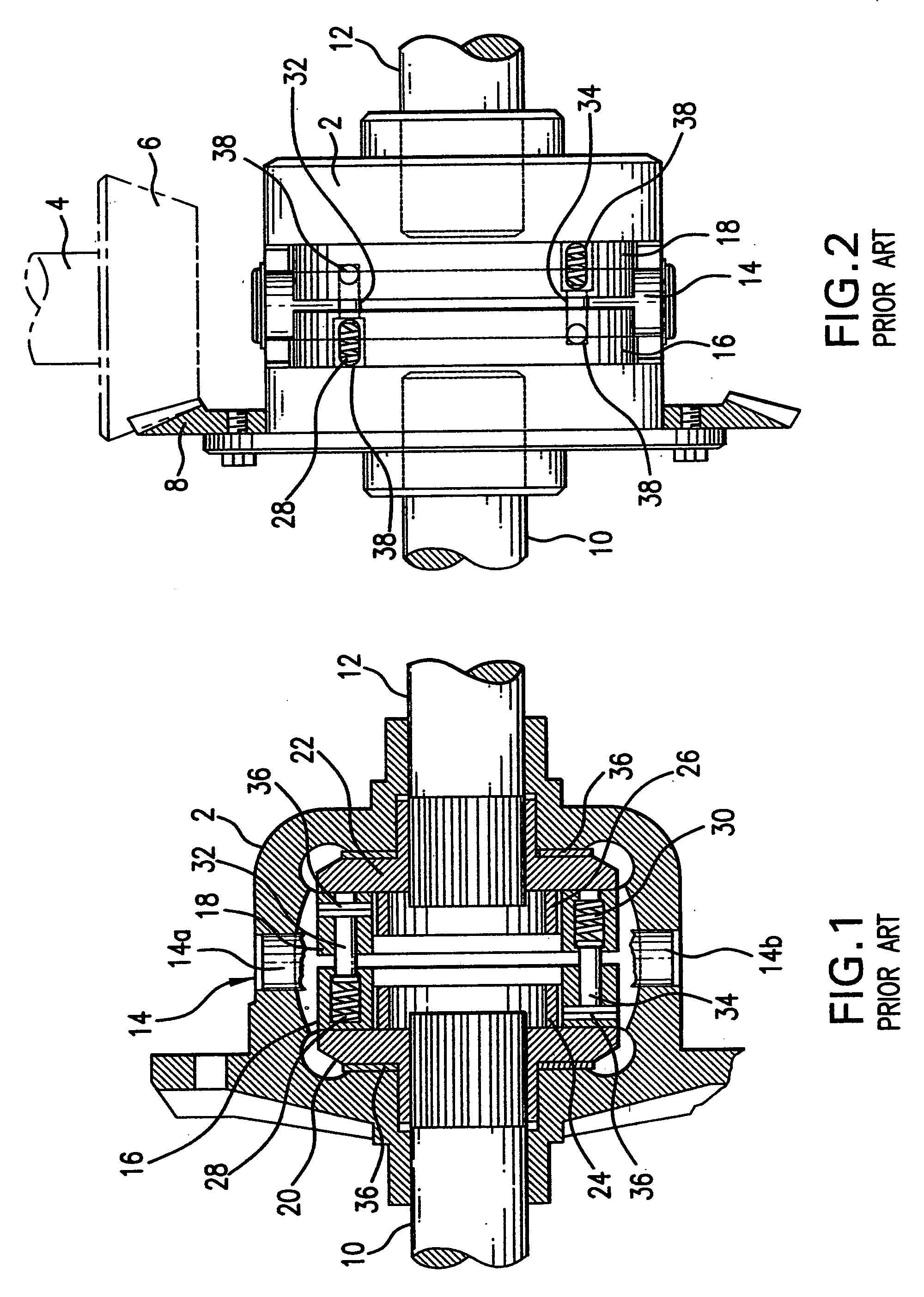
[0039]Referring first to FIGS. 1 and 2, as illustrated and described in the prior Dissett U.S. Pat. No. 5,715,733, the disclosure of which is incorporated herein, the known locking differential includes an outer housing 2 that is rotatably driven from the drive shaft 4 via pinion 6 and ring gear 8. A pair of output shafts are normally rotatably driven at the same speed by the housing via transverse drive rod 14 having end portions 14a and 14b supported in corresponding openings contained in the housing; a pair of annular clutch members 16 and 18 the adjacent faces of which contain diametrically extending grooves that receive the drive rod; and a pair of side gears 20 and 22 that are non-rotatably splined to the output shafts 10 and 12, respectively. The clutch members are mounted for axial sliding displacement on annular spacer members 24 and 26, which clutch members are normally biased apart by compression springs 28 and 30 that react on spring pins 32 and 34, respectively, thereby...


PUM


Abstract

A locking differential includes a pair of annular clutch members that are normally displaced apart to effect engagement between clutch teeth on the remote ends of the clutch members and corresponding gear teeth on the adjacent ends of a pair of side gears between which the clutch members are colinearly arranged. When one output shaft overruns the other by a predetermined amount, the clutch member associated with the overrunning output shaft is disengaged from its associated side gear. A retaining device retains the clutch members in the disengaged condition until the overrunning condition is terminated. In one embodiment, the retaining device is a cam arm and follower pin arrangement that is connected between the clutch members and operates in conjunction with a pair of friction rings. In a second embodiment, the retaining device comprises a pair of holdout rings that operate between the clutch members and the side gears.

Description

BACKGROUND OF THE INVENTION[0001]1. Field of the Invention[0002]A locking differential includes a pair of annular clutch members that are normally displaced apart to effect engagement between clutch teeth on the remote ends of the clutch members and corresponding gear teeth on the adjacent ends of a pair of side gears between which the clutch members are colinearly arranged. When one output shaft overruns the other by a predetermined amount, the clutch member associated with the overrunning output shaft is disengaged from its associated side gear. A retaining device retains the clutch members in the disengaged condition until the overrunning condition is terminated. In one embodiment, the retaining device is a cam arm and follower pin arrangement that is connected between the clutch members and operates in conjunction with a pair of friction rings. In a second embodiment, the retaining device comprises a pair of holdout rings that operate between the clutch members and the side gear...

Claims


Application Information

Patent Timeline
Patent Type & Authority Applications(United States)
IPC IPC(8): F16H48/06F16D21/08F16H48/20F16H48/12
CPCF16D7/044Y10T74/19005F16H48/142F16H48/14
Inventor BAWKS, JAMES R.
Owner EATON CORP
Why Eureka
Try Eureka