Cleaning apparatus and method for high-speed rotational atherectomy devices

a high-speed rotational atherectomy and cleaning apparatus technology, applied in the field of high-speed rotational atherectomy devices, can solve the problems of reducing the cutting efficiency of the abrasive cutting surface, affecting and affecting the recovery of patients, so as to maximize the efficiency of tissue removal

Inactive Publication Date: 2009-01-08
CARDIOVASCULAR SYST INC
View PDF18 Cites 69 Cited by
  • Summary
  • Abstract
  • Description
  • Claims
  • Application Information

AI Technical Summary

Benefits of technology

This patent describes how to make a better tool that can remove blockages in arteries caused by plaque buildup. It has a special part at its front called a cutter which helps scrape off the plaque. There are also guides and other tools used to help move this new technology through the patient's blood vessels. Overall, this makes a more efficient way to clear these blockages without causing damage to the surrounding tissues.

Problems solved by technology

The technical problem addressed in this patent text relates to improving the effectiveness of rotational atherectomy procedures in treating stenotic materials in arteries and other bodily passages. These procedures involve the use of abrasive cutting surfaces that may become blocked or reduced in efficacy when trying to remove stenotic material. Therefore, there is a need to provide better methods and tools to clean the abrasive cutting surface and restore its original performance level.

Method used


Image

  • Cleaning apparatus and method for high-speed rotational atherectomy devices
  • Cleaning apparatus and method for high-speed rotational atherectomy devices
  • Cleaning apparatus and method for high-speed rotational atherectomy devices

Examples


Embodiment Construction

[0022]While the invention is amenable to various modifications and alternative forms, specifics thereof are shown by way of example in the drawings and described in detail herein. It should be understood, however, that the intention is not to limit the invention to the particular embodiments described. On the contrary, the intention is to cover all modifications, equivalents, and alternatives falling within the spirit and scope of the invention.

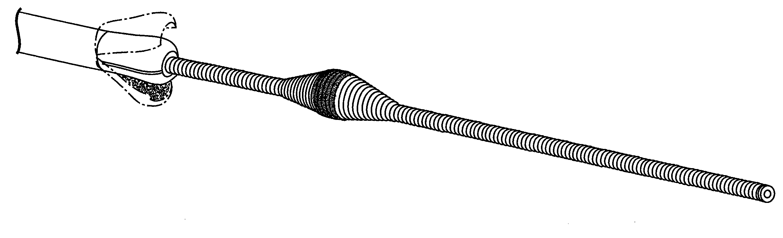
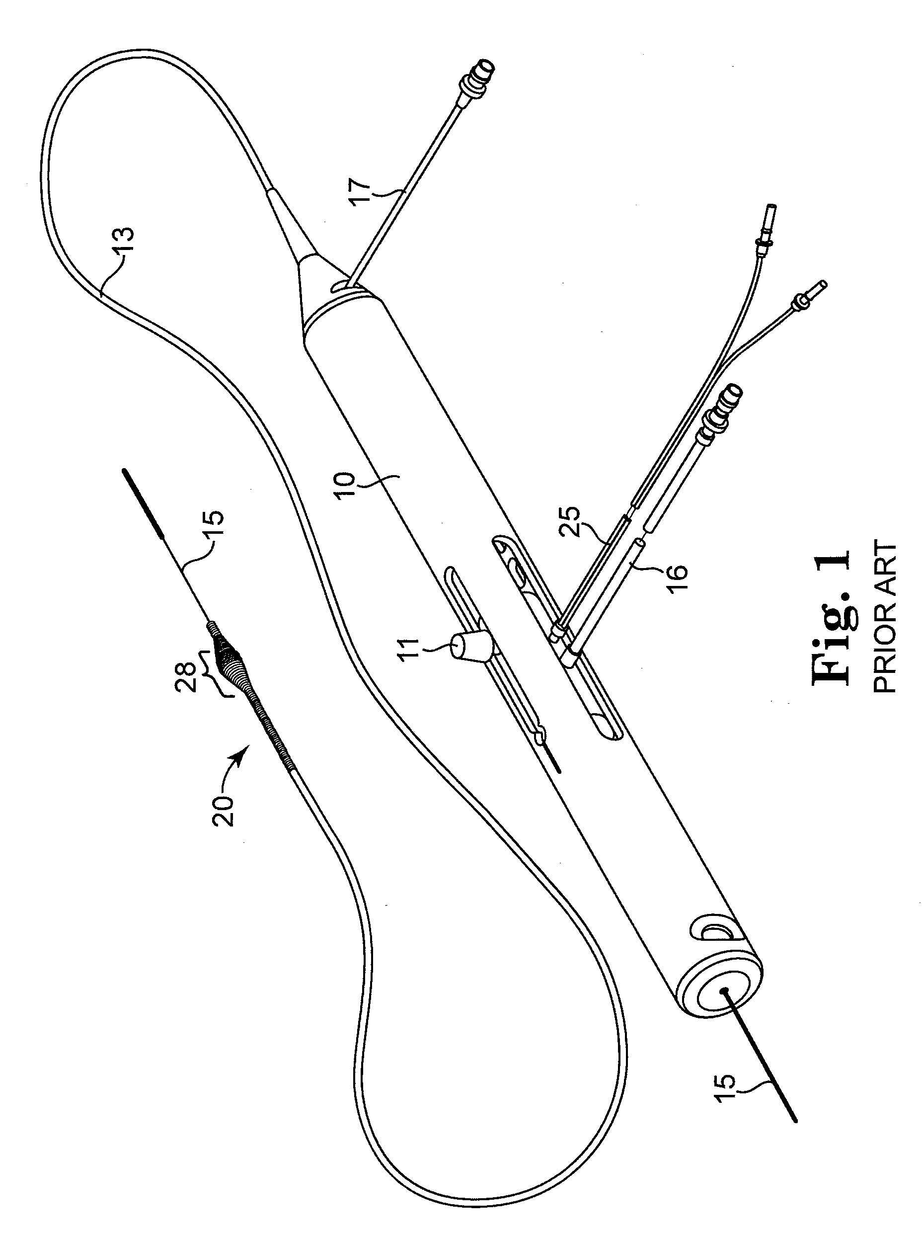
[0023]FIG. 1 illustrates a typical and exemplary rotational atherectomy device that may utilize the present invention. Such a device is generally described in U.S. Pat. No. 5,314,438 (Shturman) and U.S. Pat. No. 6,494,890 (Shturman), the disclosures of each incorporated herein by reference in their entirety.

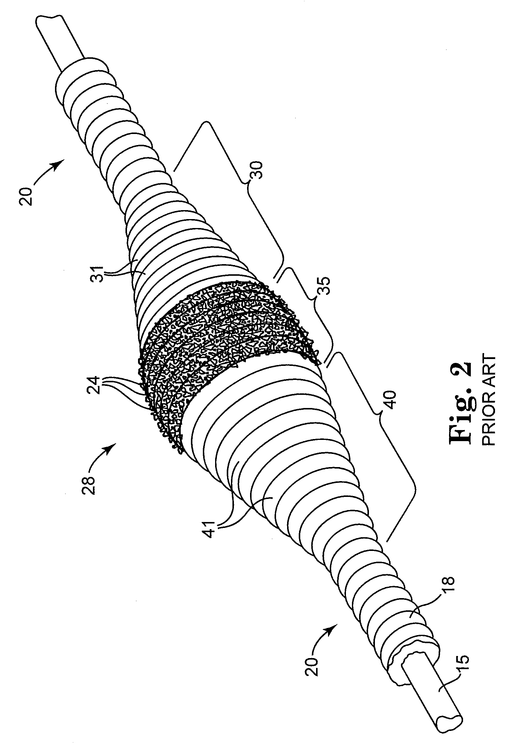
[0024]The exemplary rotational atherectomy device of FIG. 1 includes a handle portion 10, an elongated, flexible drive shaft 20, an enlarged cutting section 28, and an elongated catheter 13 extending distally from the handle portion 10. En...


PUM


Abstract

Apparatus and method for maximizing efficiency of tissue removal from body passageways is provided. A rotational atherectomy device comprises, inter alia, an elongated, flexible and rotatable drive shaft with an enlarged cutting surface disposed thereon, guide wire and catheter. The distal end of catheter may have a cutting surface cleaner, either attached thereto or integrated therein. The cleaner may be outwardly radially flexible and biased against the drive shaft. The cleaner may be opened to accommodate the enlarged cutting surface for cleaning particles trapped therein as a consequence of abrading as it is either advanced distally over the drive shaft and/or the drive shaft is retracted proximally toward the cleaner to accommodate the diameter of the enlarged cutting section. The cleaner comprises an inner surface having an abrasive surface for mechanically scraping and dislodging material trapped in the enlarged cutting head tissue removing surface.

Description


Claims


Application Information

Patent Timeline
Owner CARDIOVASCULAR SYST INC
Why Eureka
Try Eureka