Power Tool

a technology of power tools and guiding devices, which is applied in the field of power tools, can solve the problems of laser mechanical stress, inconvenient operation, and inability to accurately guide, and achieve the effects of reducing vibration impairment, excellent quality, and mechanical stress reduction of guiding devices

Inactive Publication Date: 2009-01-15
ANDREAS STIHL AG & CO KG
View PDF20 Cites 5 Cited by
  • Summary
  • Abstract
  • Description
  • Claims
  • Application Information

AI Technical Summary

Benefits of technology

[0007]The low-vibration arrangement of the guiding device on the power tool has the result that only minimal vibrations are transmitted onto the guiding device. In this way, the mechanical stress on the guiding device is reduced, on the one hand, and impairment of guiding as a result of vibrations is reduced, on the other hand. In a simple way, a guiding action of excellent quality can be achieved.
[0008]Advantageously, the guiding device is secured on the power tool in a low-vibration area of the power tool. With the targeted selection of the area in which the guiding device is secured on the power tool, the vibrations transmitted onto the guiding device can be minimized. Usually, in operation of the power tool at least one section of the power tool vibrates in at least one direction in the form of a standing wave. A low-vibration arrangement of the guiding device on the power tool can be achieved in a simple way in that the guiding device is arranged in the area of a node of the standing wave. In the area of the node of the standing wave the amplitude is zero. In the adjoining areas, the resulting amplitudes are also very low so that an arrangement of the guiding device at the node, or closely adjacent to the node, is expedient in order to achieve a minimal vibration load of the guiding device. By a suitable selection of the arrangement of the guiding device, a minimal transmission of vibrations onto the guiding device can be achieved in a simple way.

Problems solved by technology

In operation of such a motor-driven power tool vibrations are generated.
On the one hand, these vibrations cause mechanical stress on the laser and, on the other hand, they cause imprecise guiding.

Method used


Image

  • Power Tool
  • Power Tool
  • Power Tool

Examples


Embodiment Construction

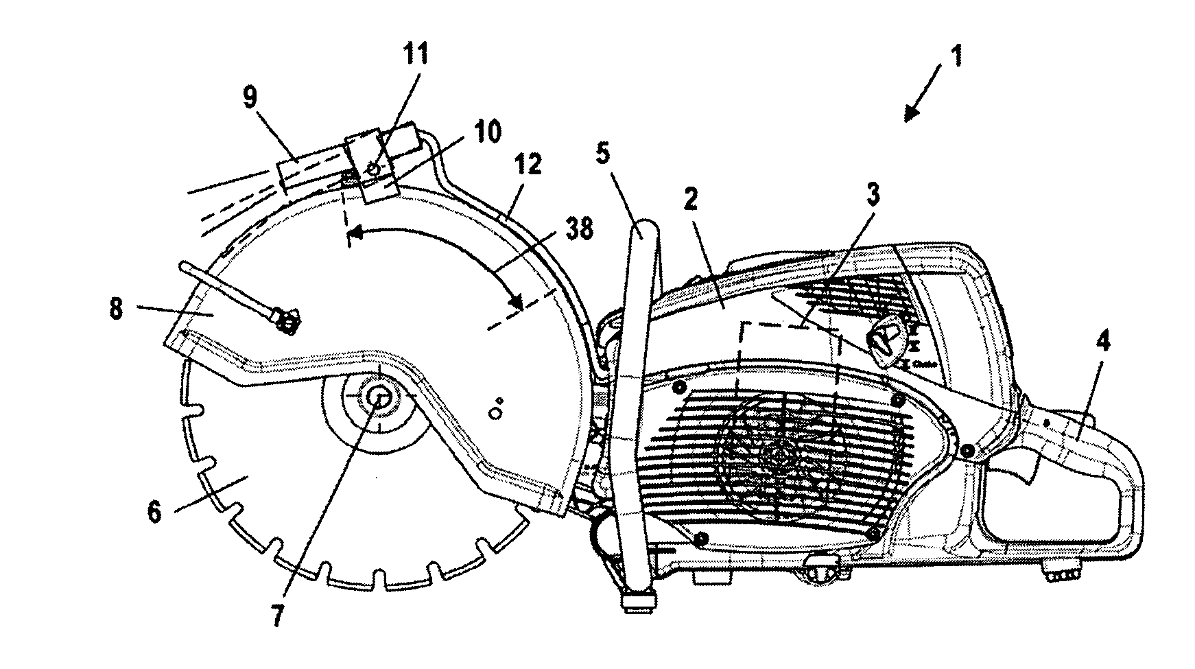
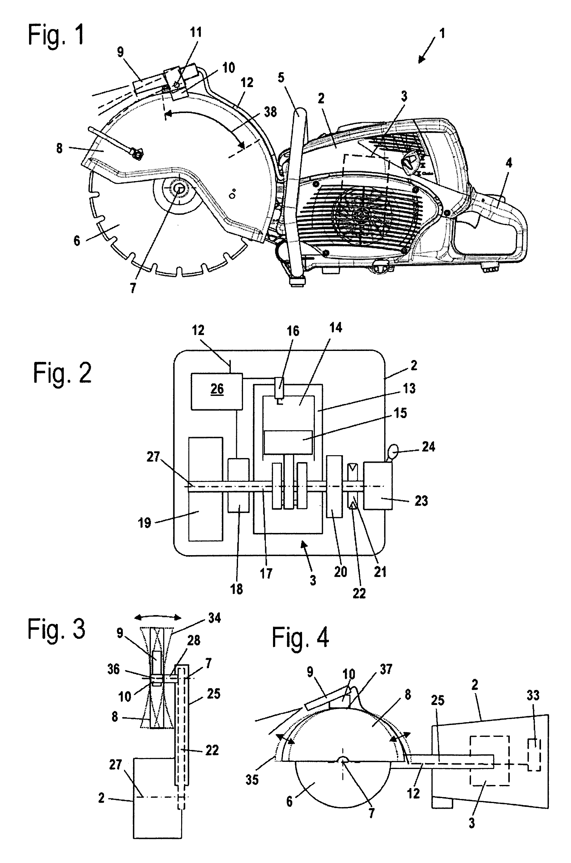
[0024]In FIG. 1 a power tool in the form of a cut-off machine 1 is shown. The cut-off machine 1 has a housing 2 in which a drive motor 3 is arranged. The drive motor 3 is embodied as an internal combustion engine. On the housing 2 handles, i.e., a rear handle 4 and a grip pipe 5, are secured. The rear handle 4 and the grip pipe 5 are connected to the drive motor 3 by means of vibration damping elements, not shown. The vibration damping elements can be secured between the handles and the housing 2, between the housing 2 and the drive motor 3, or between a part of the housing 2 where the handles are secured and a further part of the housing 2 where the drive motor is secured.

[0025]The cut-off machine 1 has a cutting wheel 6 as a work tool that is rotatingly driven by the drive motor 3 about axis of rotation 7. The cutting wheel 6 is partially covered by a protective cover 8. The protective cover 8 extends about half of the circumference of cutting wheel 6 and covers also the lateral f...


PUM

PropertyMeasurementUnit
angleaaaaaaaaaa
areaaaaaaaaaaa
speedaaaaaaaaaa

Abstract

A power tool has a drive motor that drives a tool and an optical guiding device secured on the power tool in alignment relative to the work tool. The guiding device is arranged in a low-vibration arrangement on the power tool and is in particular secured on the power tool in a low-vibration area of the power tool. At least one section of the power tool vibrates in the form of a standing wave in at least one direction, wherein the low-vibration area where the guiding device is arranged is the area of a node of the standing wave.

Description

BACKGROUND OF THE INVENTION[0001]The invention concerns a power tool comprising a drive motor that drives a work tool and comprising an optical guiding device that is secured on the power tool in alignment relative to the work tool.[0002]DE 10 2004 002 747 A1 discloses a motor chainsaw that comprises a laser for measuring partial lengths of a workpiece wherein the laser generates a laser dot as a visual aid on the workpiece. The laser is fixedly connected to the housing by a holder.[0003]In electric power tools such as electric hand-held circular saws or electric jigsaws, lasers are known as a guide for the cutting direction. The lasers are fixedly mounted on the housing of the power tool.[0004]In operation of such a motor-driven power tool vibrations are generated. On the one hand, these vibrations cause mechanical stress on the laser and, on the other hand, they cause imprecise guiding.[0005]The invention has the object to provide a power tool of the aforementioned kind whose guid...

Claims


Application Information

Patent Timeline
Patent Type & Authority Applications(United States)
IPC IPC(8): B26D7/00B23Q5/00B25D17/10
CPCB23D59/003B23D47/005Y10T83/869B23D59/002B23Q17/24B24B49/12
Inventor ROSSKAMP, HEIKOELFNER, JORGSCHIERLING, ROLANDBAUER, PETER
Owner ANDREAS STIHL AG & CO KG
Why Eureka
Try Eureka