
Dual linear actuator

a dual-line actuator and actuator technology, applied in the direction of fluid couplings, gearings, servomotors, etc., can solve the problem of not being able to use the shown dual actuator for the movement, and achieve the effect of high regulating torque, increased regulating accuracy, and high regulating speed

Active Publication Date: 2009-01-15
AIRBUS OPERATIONS GMBH
View PDF7 Cites 14 Cited by
  • Summary
  • Abstract
  • Description
  • Claims
  • Application Information

AI Technical Summary

Benefits of technology

The present invention provides an actuator that combines the movements of linear actuators with parallel longitudinal axes, allowing for high regulating speed, torque, and accuracy. The actuator can be stopped at one or more predetermined positions. The actuator can also be designed for long regulating distances and high precision, or for short regulating distances and high torque. The actuator can be expanded by a spindle drive that acts in axial direction, allowing for a shared direction of deflection. The actuator can also be designed for high regulating speed and torque, or for high precision. These technical effects make the actuator suitable for various applications.

Problems solved by technology

While this dual actuator combines two different movement components, they can however not be used for a common linear movement that would be helpful to the application, mentioned as an example, on high-lift components of an aircraft.
Therefore it would also not be possible to use the shown dual actuator for the movement, mentioned as an example, of high-lift components of an aircraft, in which movement the advantages of high regulating speed and high regulating accuracy are required, either together or separately, in a single movement direction.

Method used


Image

  • Dual linear actuator
  • Dual linear actuator
  • Dual linear actuator

Examples


Embodiment Construction

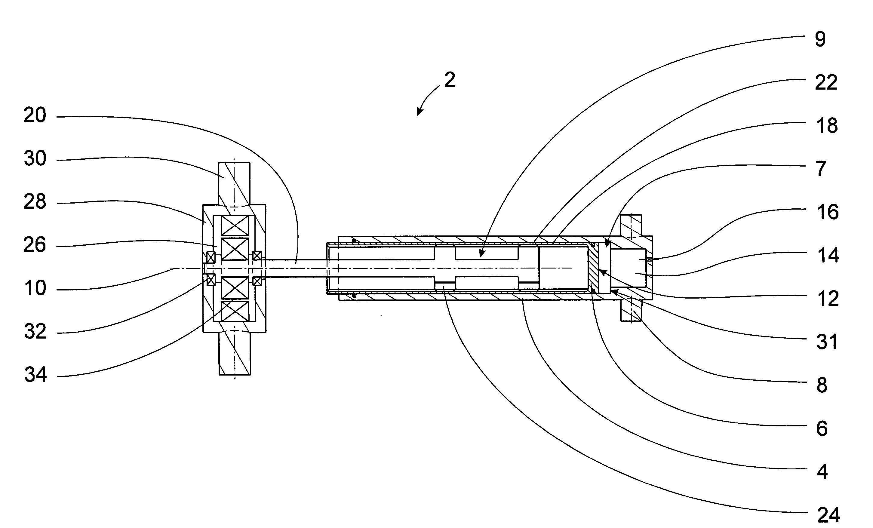
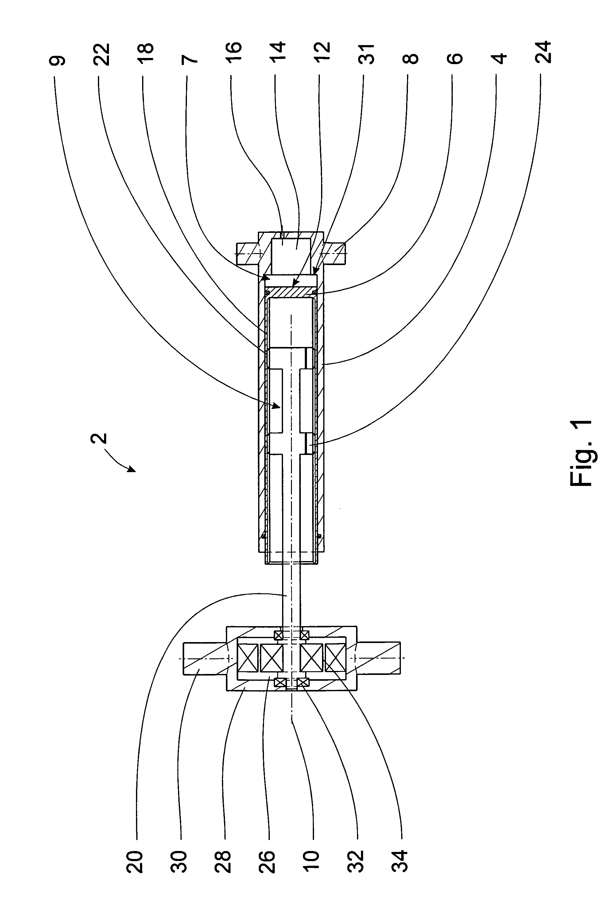
[0016]The dual linear actuator 2 according to the invention, which actuator 2 is shown in FIG. 1, as an example comprises a cylinder 4 and a tubular piston element 6 which form the first movement component 7. On the side which is the right-hand side shown in FIG. 1 the cylinder 4 comprises fastening elements 8, which are, for example, designed as cylindrical trunnions that face each other.

[0017]On the side facing the fastening elements 8 the piston element 6 comprises a closed piston face 12 that points towards a hollow space 14 in the cylinder 4. By means of a control valve (not shown), a pressurised fluid can be fed into this hollow space 14 by way of an opening 16 in the cylinder, in which hollow space 14 said fluid exerts a force onto the piston face 12 in order to move the piston element.

[0018]On the inside of the piston element 6 there is a spindle thread 18 which is engaged by an elongated spindle element 20 with shoulders 24 that comprise a corresponding thread 22. The spind...


PUM


Abstract

An actuator having two or more interconnected movement components, wherein the movement components are designed as linear actuators with substantially coaxial longitudinal axes or longitudinal axes that are parallel to each other and that are interconnected in longitudinal direction such that their linear movements are superimposed on one another, and such that at least one of the linear actuators can be stopped at one or several predetermined positions.

Description

CROSS-REFERENCE TO RELATED APPLICATIONS[0001]This application claims the benefit of the filing date of German Patent Application No 10 2007 027 698.4 filed 15 Jun. 2007, the disclosure of which application is hereby incorporated herein by reference.FIELD OF THE INVENTION[0002]The invention relates to an actuator comprising two or more interconnected movement components.BACKGROUND OF THE INVENTION[0003]Such actuators may, for example, be used as regulating drives for moving high-lift components of wings of modern commercial aircraft or transport aircraft. The term “movement component” also refers to a servomotor or actuator that forms a component of the actuator according to the invention and for this reason is referred to as a “movement component”. An actuator created from the combination of two or more movement components would combine the advantages inherent in the individual movement components and in this way would make it possible to provide an improved regulating drive. Advant...

Claims


Application Information

Patent Timeline
Patent Type & Authority Applications(United States)
IPC IPC(8): F15B13/00
CPCF15B15/088Y10T74/18584F15B18/00
Inventor SCHLIPF, BERNHARDHEINTJES, MARK
Owner AIRBUS OPERATIONS GMBH
Learn More