Heat exchanger arrangement

a technology of heat exchanger and insulating plate, which is applied in the direction of stationary tubular conduit assembly, stationary conduit assembly, stationary plate conduit assembly, etc., can solve the problems of increasing the total engine heat load, increasing the air temperature, and reducing the possibility of motor performan

Inactive Publication Date: 2009-01-15
JOO DE DEUS & FILHOS
View PDF14 Cites 59 Cited by
  • Summary
  • Abstract
  • Description
  • Claims
  • Application Information

AI Technical Summary

Benefits of technology

[0011]The object of the invention is thus to prov

Problems solved by technology

However, such compression of air also increases the air temperature.
This might increase the total engine heat load or decrease the possible motor performanc

Method used


Image

  • Heat exchanger arrangement
  • Heat exchanger arrangement
  • Heat exchanger arrangement

Examples


Embodiment Construction

[0032]Throughout the description and the drawings, reference numbers will be maintained for same or functionally similar elements.

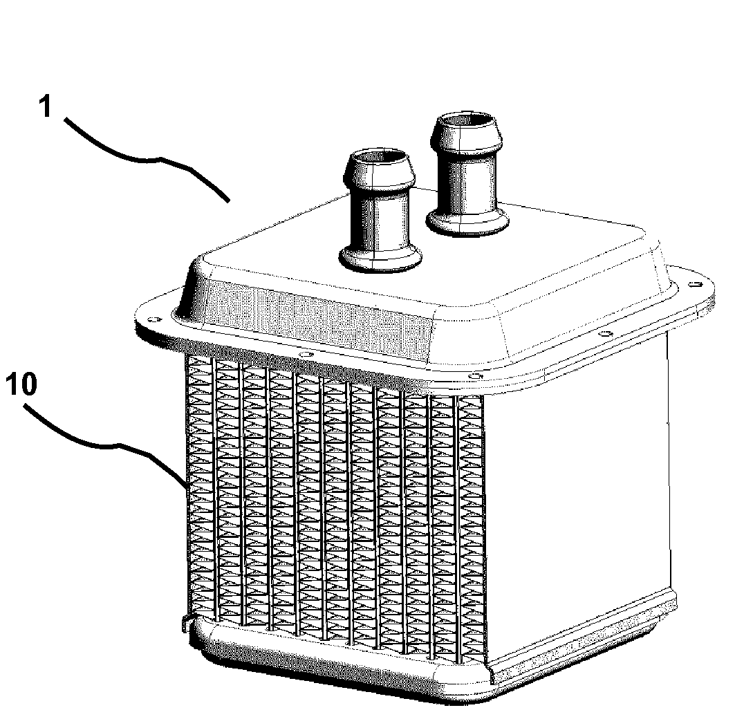
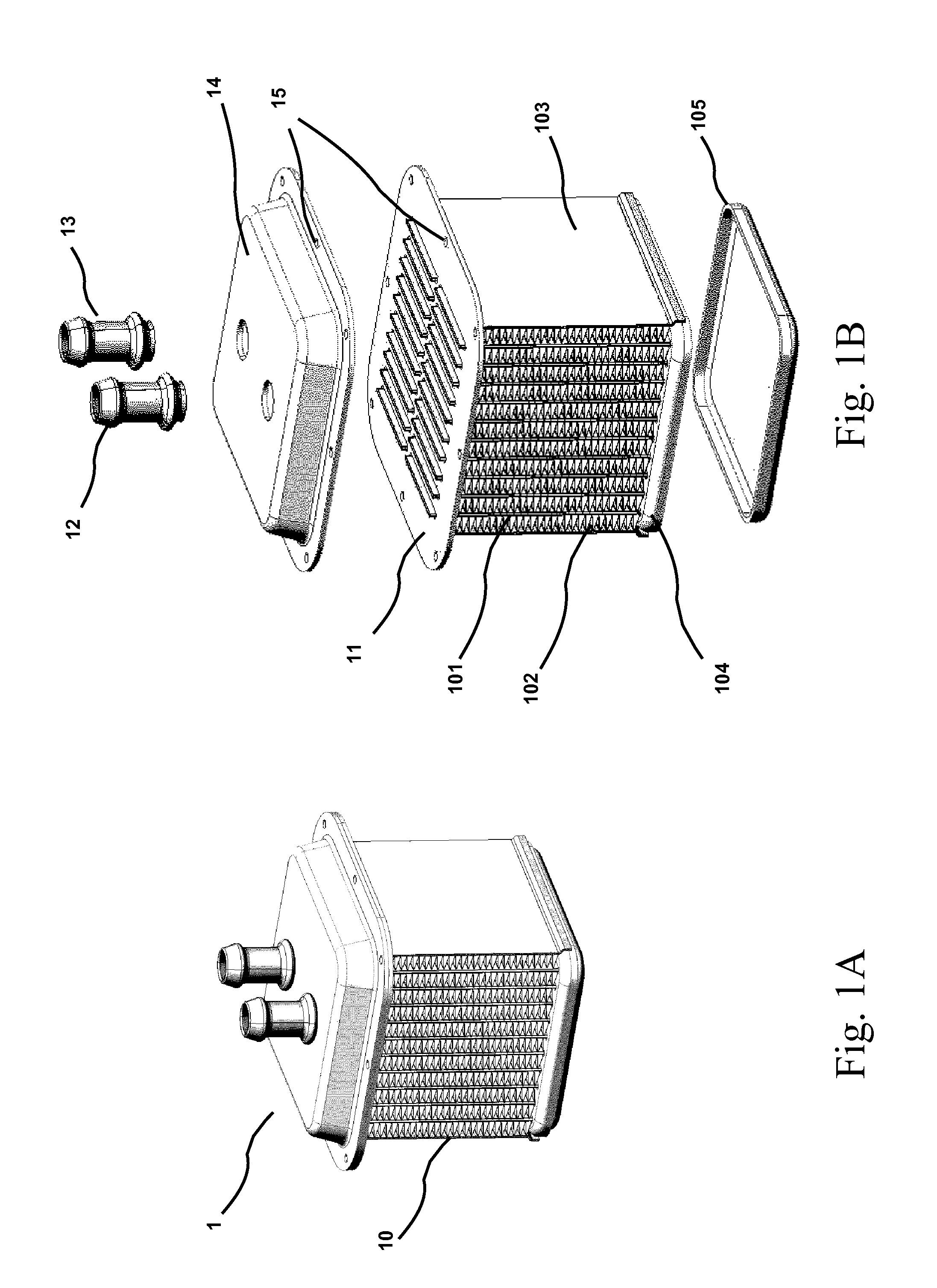
[0033]FIGS. 1A and 1B show a charge cooler 1 of a heat exchanger arrangement consisting of a brazed aluminum cooler core 10 and a header plate 11.

[0034]Specifically, the cooler core 10 comprises a plurality of tubes 101 and fins 102.

[0035]Preferably, the cooler core 10 comprises also two side plates 103, a bottom plate 104 and a lower tank 105.

[0036]In a preferred embodiment, the cooler core 10 is manufactured by assembling the various parts and then brazing the cooler core assembly.

[0037]By attaching an upper tank 14 to the header plate 11 of the charge cooler 1 a hermetically sealed circulation system for a coolant is created. Specifically, the upper tank comprises an entry duct 12 and an exit duct 13 for connecting external tubes.

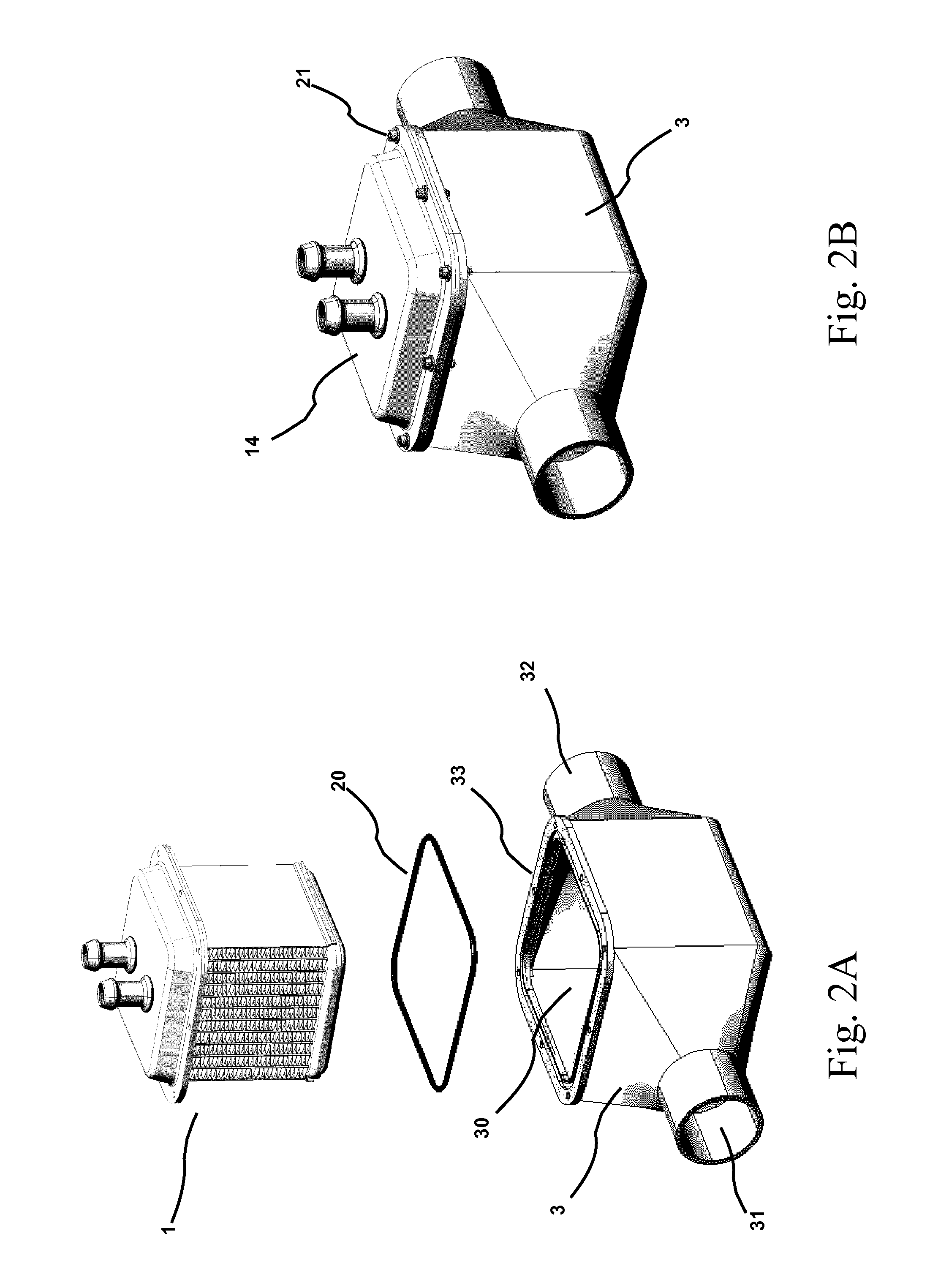
[0038]Preferably, the upper tank 14 is assembled to the core 10 before brazing.

[0039]In the exemplary embodiment, the upper ...


PUM


Abstract

A heat exchanger arrangement comprising a charge cooler and a housing. The charge cooler comprises a charge cooler core, a header plate, a coolant entry duct and a coolant exit duct. Specifically, the charge cooler core comprises hallow heat-transfer elements through which a coolant can flow. The housing is in the form of a chamber with a single aperture for receiving the cooler core and comprises an air entry duct, an air exit duct and a flange. The cooler core is fixed inside the housing by fixing the header plate of the charge cooler to the flange of the housing. Additionally, the header plate of the charge cooler closes the single aperture for receiving the cooler core.

Description

CROSS-REFERENCE TO RELATED APPLICATIONS[0001]This application claims benefit of European patent application number 07398010.4, filed Jul. 11, 2007, which is herein incorporated by reference.BACKGROUND OF THE INVENTION[0002]1. Field of the Invention[0003]The invention relates to heat exchanges such as intercoolers or charge air / coolant coolers. More specifically the invention relates to an arrangement of a charge cooler allowing for a simplified assembly of the charge cooler core in its housing.[0004]2. Description of the Related Art[0005]Heat exchangers, such as charge air cooler are well known in the art. For example, in modern diesel engines a turbocharger compresses the output air of the engine in order to provide an increased mass flow of air to the engine, which allows for increasing the combustion of fuel and consequently performance. However, such compression of air also increases the air temperature. This might increase the total engine heat load or decrease the possible mot...

Claims


Application Information

Patent Timeline
IPC IPC(8): F28F9/00
CPCF02B3/06F02B29/0462F02B37/00F28D7/1623F28D9/0043Y02T10/146F28D2021/0082F28F9/0075F28F9/013F28F9/0224F28D9/0056Y02T10/12
Inventor PIMENTEL, EDUARDO ALBERTO NUNES MENDESCAVACA, HELDER JOSE TRINDADE
Owner JOO DE DEUS & FILHOS
Why Eureka
Try Eureka