Breather-sampling-filler assembly for liquid reservoirs/systems

Inactive Publication Date: 2009-01-15
GASOLINEINK USA
View PDF25 Cites 24 Cited by
  • Summary
  • Abstract
  • Description
  • Claims
  • Application Information

AI Technical Summary

Benefits of technology

[0008]The present invention minimizes the issues outlined above and provides an improved breather-sampling-filler assembly for use with a variety of liquid lubrication systems. The assemblies of the invention permit efficient filling and sampling operations, while essentially eliminating the potential of spills, atmospheric liquid contamination and air pollution, and introduction of dirt or other solid contaminants into the lubrication system liquid. Furthermore, the invention also allows for attachment of auxiliary oil reconditioning equipment while a system is operation versus having to shutdown the system to attach the equipment. Broadly speaking, preferred forms of the breather-sampling-filler assemblies of the invention are designed for attachment and securement to a liquid lubrication system and consist of a base unit having a breather port, a liquid fill port, and a liquid sampling port that all communicate with the interior of the lubricat

Problems solved by technology

However accomplished, conventional lubrication system filling and sampling exposes the liquid within the lubrication system to the atmosphere and also often leads to contamination of the liquid in the reservoir and lubrication system.
In addition, because conventional reservoir openings will accept a variety of different delivery equipment, it is possible that a given lubrication system may be improperly filled with the wrong liquid.
For example, a hydraulic fluid reservoir may be mistakenly filled with non-hydraulic oil or the like, which can create equipment and/or component failure.
Another deficiency with conventional capped liquid lubrication systems is ingression of airborne solid and l

Method used


Image

  • Breather-sampling-filler assembly for liquid reservoirs/systems
  • Breather-sampling-filler assembly for liquid reservoirs/systems
  • Breather-sampling-filler assembly for liquid reservoirs/systems

Examples


Example

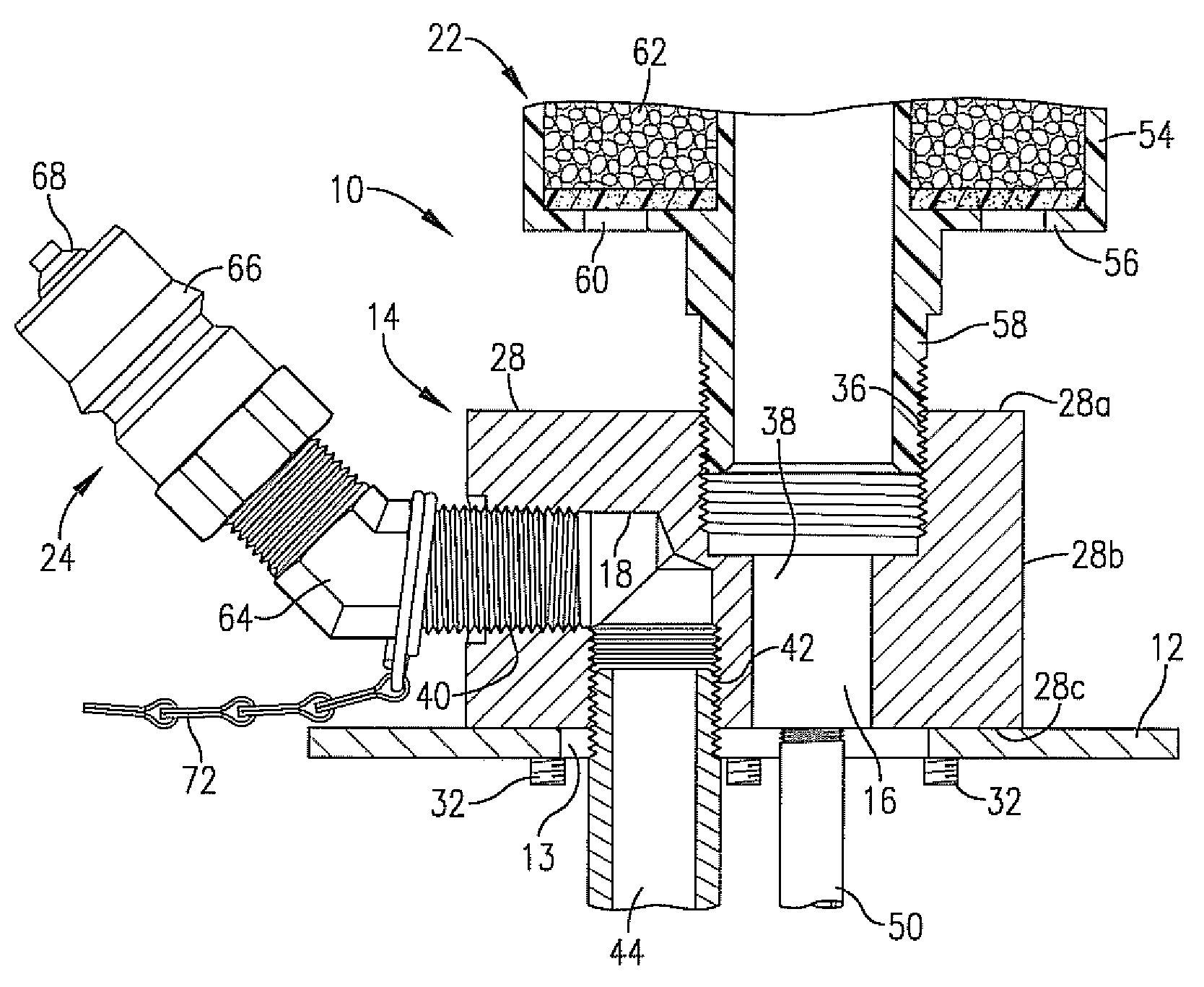
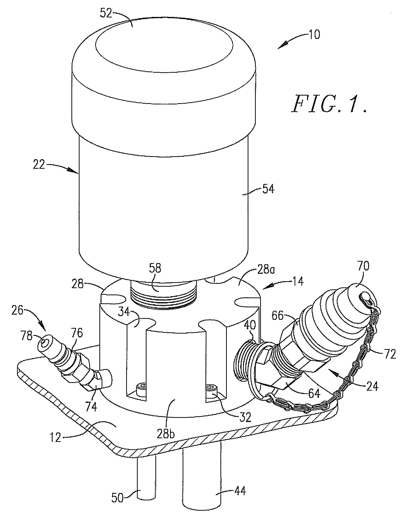
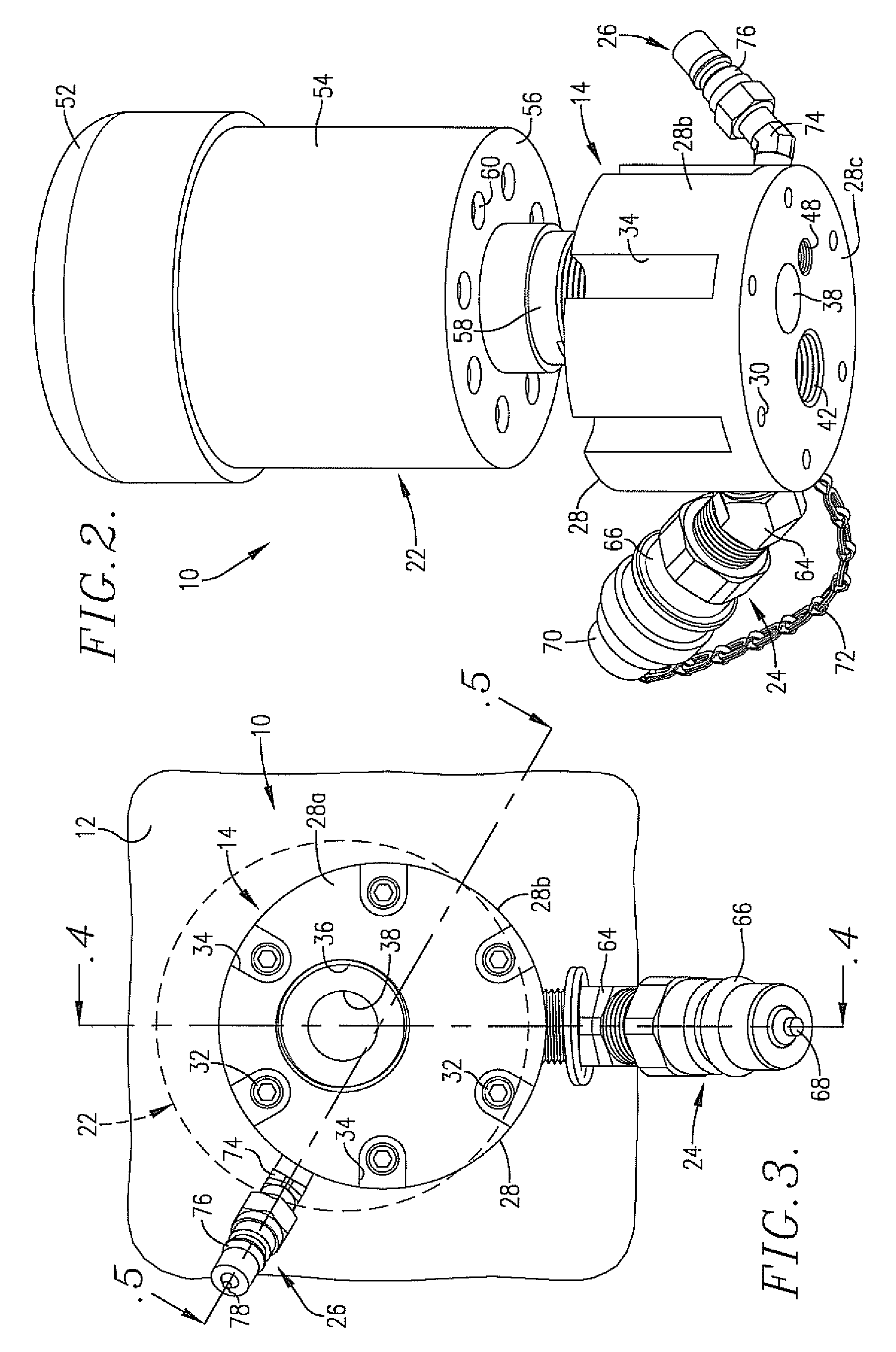
[0015]Turning now to the drawings, a breather-sampling-filler assembly 10 in accordance with the invention is designed for permanent or semi-permanent attachment to a wall 12 forming a part of a liquid lubrication system adjacent an access opening 13 therethrough, such as a hydraulic fluid reservoir (as used herein, A lubrication system refers to all types of lubricant-holding structures including conventional lubrication systems and reservoirs). Broadly speaking, the assembly 10 includes a primary block or unit 14 having individual breather, fill, and sampling ports 16, 18, and 20. Also, the assembly 10 has a breather 22 operably secured to the breather port 16; a fill assembly 24 operably secured with fill port 18; and a sampling assembly 26 operably secured with sampling port 20.

[0016]In detail, the unit (block) 14 is preferably a solid metal, generally cylindrical block 28 having top wall surface 28a, sidewall surface 28b, and bottom wall surface 28c, with a total of six circumf...


PUM


Abstract

A breather-sampling-filler assembly (10) for liquid lubrication systems is provided which includes a primary unit (block) (14) adapted for permanent or semi-permanent attachment to a wall (12) of a lubrication system in covering relationship to a lubrication system access opening (13). The unit (14) includes individual breather, fill, and sampling ports (16, 18, 20), and is designed to support a breather (22) in communication with breather port (16), a fill assembly (24) in communication with fill port (18), and a sampling assembly (26) in communication with sampling port (20). The breather (22) includes at least one vent opening (60) and had a selected media (62) therein for desired treatment of solid and liquid airborne contaminants passing into and out of the lubrication system. Use of the assembly (10) permits continuous treatment of air entering and leaving the lubrication system (12), and also allows quick, trouble-free liquid filling and sampling while avoiding introduction of contaminants into the lubrication system liquid and air pollution from the lubrication system (12)

Description

BACKGROUND OF THE INVENTION[0001]1. Field of the Invention[0002]The present invention is broadly concerned with breather-sampling-filler assemblies adapted for permanent or semi-permanent attachment to a liquid lubrication system such as to a hydraulic fluid reservoir so as to permit fluid filling, liquid sampling and on-line oil reconditioning without the need for opening the lubrication system, thus greatly reducing spills and the ingression of liquid and solid contamination into the lubrication system. The sampling port allows for efficient and repeatable sampling practices and results. The assemblies also include a breather element serving to minimize and trap solid and liquid contaminants from the atmosphere passing into the lubrication system.[0003]2. Description of the Prior Art[0004]Most liquid lubrication systems are equipped with a filler opening which is capped using a threaded plug, screw on filler cap, or a quick disconnect fitting. When the lubrication system is to be ...

Claims


Application Information

Patent Timeline
IPC IPC(8): F16N21/00
CPCB01D2259/4516G01N2001/205G01N2001/1037G01N1/10
Inventor WHIGHAM, JOHN C.
Owner GASOLINEINK USA
Why Eureka
Try Eureka