Vibration actuator and drive unit including the same

a technology of vibration actuator and drive unit, which is applied in piezoelectric/electrostrictive/magnetostrictive devices, piezoelectric/electrostriction/magnetostriction machines, electrical apparatus, etc., can solve problems such as the breakage of the piezoelectric element, and achieve the effect of preventing the concentration of stress on the soldered parts

Inactive Publication Date: 2009-01-15
PANASONIC CORP
View PDF2 Cites 15 Cited by
  • Summary
  • Abstract
  • Description
  • Claims
  • Application Information

AI Technical Summary

Benefits of technology

[0017]According to the present invention, the pressurizing element applies the compressive force in advance to the actuator body at the non-node part of the actuator body. Therefore, the vibration actuator is provided with the piezoelectric element which is less likely to break. Additionally, since the pressurizing element is made of conductive rubber including stacked insulating rubbers and conductors and the pressurizing element is arranged to bring the on-actuator body feeding electrode and the on-base feeding electrode into conduction, there is no n

Problems solved by technology

When the strain exceeds the elastic limit of the piezo

Method used


Image

  • Vibration actuator and drive unit including the same
  • Vibration actuator and drive unit including the same
  • Vibration actuator and drive unit including the same

Examples


embodiment 1

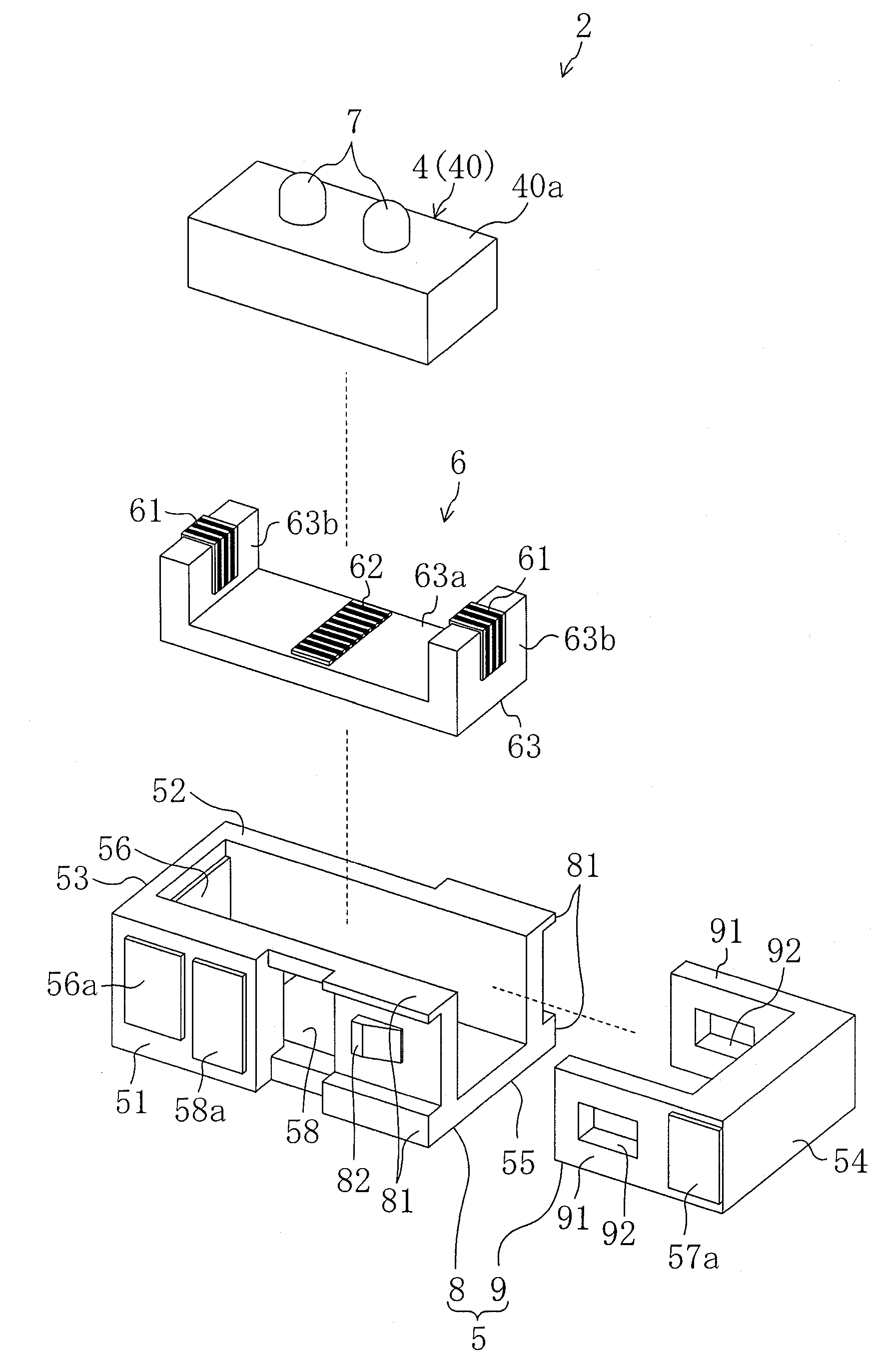
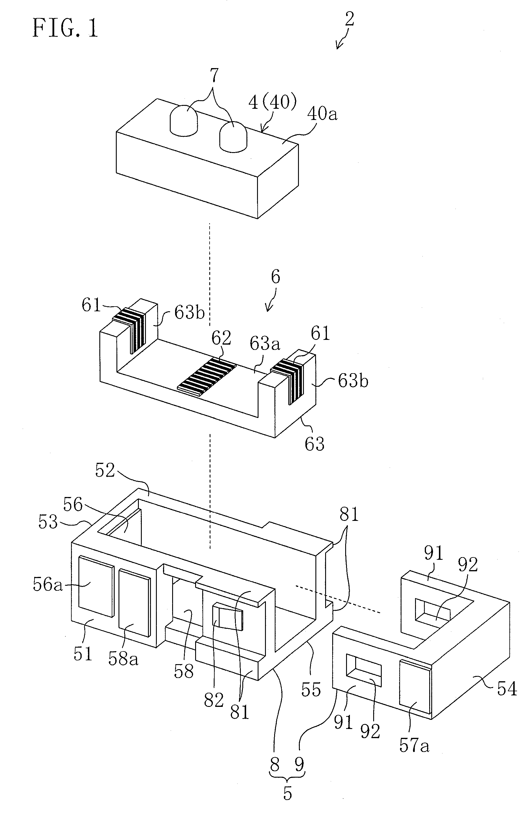
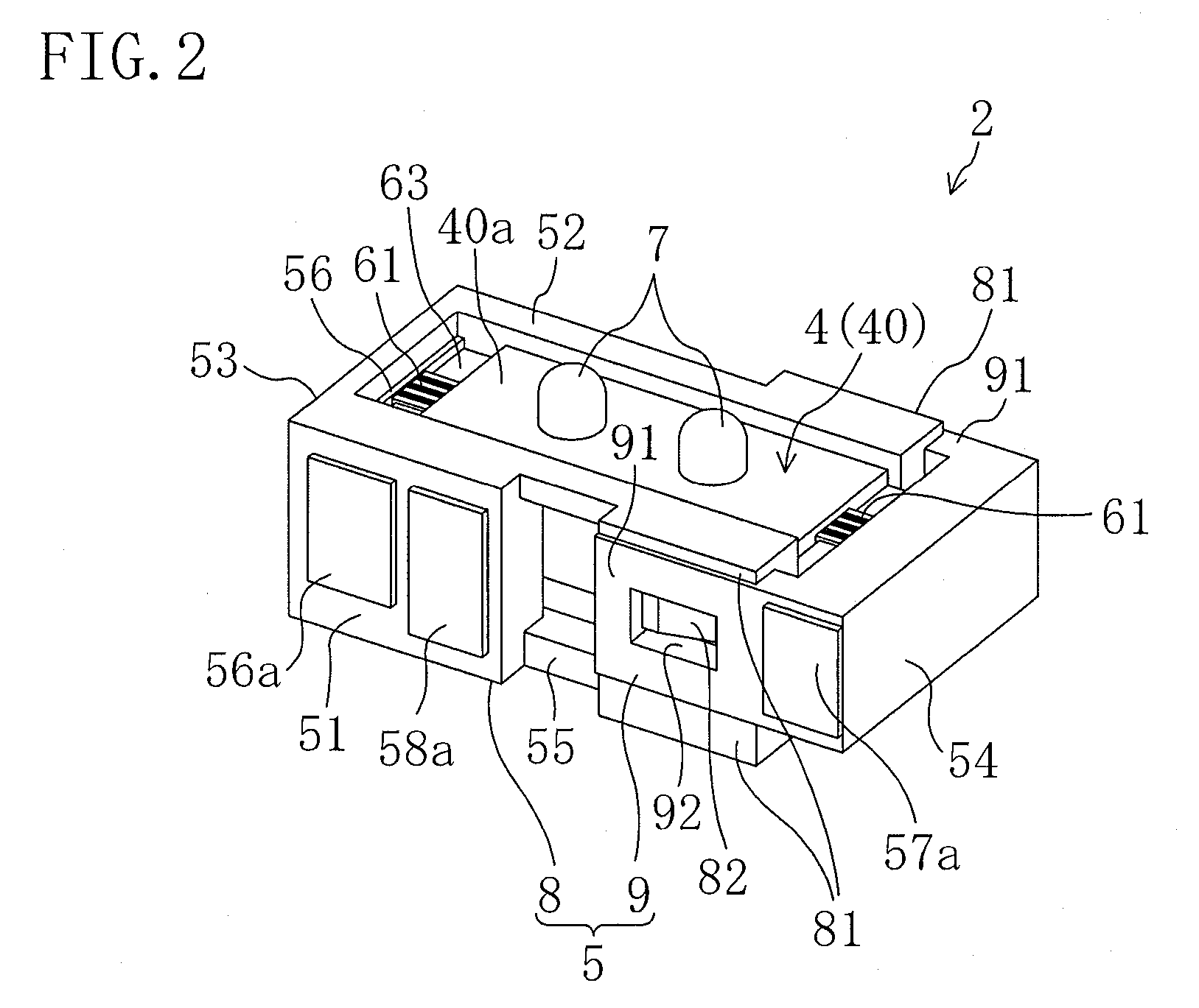
[0036]A drive unit 1 according to Embodiment 1 of the invention includes, as shown in FIG. 3, a stage 11, an ultrasonic actuator 2 and a control unit (not shown) for controlling and driving the ultrasonic actuator 2.

[0037]The stage 11 is slidably attached to guides 12 fixed in parallel with each other to a base (not shown) as a stationary body. That is, the stage 11 is movable in the extending direction of the guides 12. The extending direction of the guides 12 is the moving direction of the stage 11. The stage 11 is a plate-like member and substantially square-shaped when viewed in plan. The stage 11 is made of alumina, but the material of the stage 11 is not limited to alumina and any other material may optionally be used. The ultrasonic actuator 2 is arranged such that driver elements 7 described later come into contact with the rear surface of the stage 11 (the surface on which the guides 12 are provided). The stage 11 functions as a relative movable body which is able to move r...

embodiment 2

[0120]An ultrasonic actuator 202 of Embodiment 2 will be described below with reference initially to FIG. 13.

[0121]The ultrasonic actuator 202 of Embodiment 2 is different from that of Embodiment 1 in that the compressive force, which is applied to the actuator body 4 only in the direction of the longitudinal vibration of the actuator body 4 in Embodiment 1, is applied in the directions of the longitudinal and bending vibrations of the actuator body 4.

[0122]To be more specific, a case 205 has, at the other side in the widthwise direction thereof (the top side as shown in FIG. 13), overhangs 59 extending inwardly in the lengthwise direction of the case 205 from the first short side wall 53 and the second short side wall 54, respectively. In other words, the overhangs 59 are provided to be opposed to the long side wall 55 of the case 205.

[0123]When the actuator body 4 is placed in the case 205, pressurizing rubbers 64 which are compressed and deformed in the widthwise direction of the...


PUM


Abstract

An ultrasonic actuator includes an actuator body, a case and a support rubber. The support rubber is made of conductive rubber having alternately stacked insulating layers and conductive layers and arranged between the case and the actuator body such that an external electrode and an electrode is brought into conduction and applies in advance a compressive force in the direction of longitudinal vibration to the actuator body at a non-node part of the vibration of the actuator body. The support rubber is arranged such that the stacking direction of the conductive rubber intersects with a plane including the direction of longitudinal vibration and the direction of bending vibration of the actuator body.

Description

BACKGROUND OF THE INVENTION[0001]1. Field of the Invention[0002]The present invention relates to a vibration actuator having a piezoelectric element and a drive unit including the vibration actuator.[0003]2. Description of Related Art[0004]A vibration actuator including a piezoelectric element has been known. For example, Japanese Unexamined Patent Publication No. 2005-94956 discloses a vibration actuator.[0005]The vibration actuator according to Japanese Unexamined Patent Publication No. 2005-94956 includes an actuator body including a piezoelectric element and driver elements attached to the actuator body.[0006]The actuator body includes a plate-like piezoelectric element having a lengthwise direction. When AC voltages whose phases are different from each other are applied to two pairs of electrodes aligned along diagonal lines of the piezoelectric element, the actuator body generates longitudinal vibration in the lengthwise direction of the piezoelectric element (so-called stretc...

Claims


Application Information

Patent Timeline
IPC IPC(8): H01L41/053
CPCH01L41/0906H01L41/053H02N2/004H02N2/006H02N2/026H02N2/103H10N30/88H10N30/2023
Inventor MUKAE, HIDEAKI
Owner PANASONIC CORP
Why Eureka
Try Eureka