Integrated structure for directional wheel support and signal trigerring

a technology of integrated structure and directional wheel, applied in the field of integrated structure, can solve the problems of high manufacturing cost, complicated and bulky conventional roller device, and high manufacturing cost, and achieve the effects of reducing size, simplifying roller input structure, and facilitating fabrication and assembly

Inactive Publication Date: 2009-01-15
ZIPPY TECH
View PDF5 Cites 1 Cited by
  • Summary
  • Abstract
  • Description
  • Claims
  • Application Information

AI Technical Summary

Benefits of technology

[0004]The primary object of the present invention is to provide a structure to integrate directional wheel support and signal triggering, and simplify a roller input structure and reduce the size to facilitate fabrication and assembly, and shrink the size of products.

Problems solved by technology

However the conventional roller device is complicated and bulky.
Fabrication and assembly are difficult.
Manufacturing cost is higher.
To shrink the size of electronic products equipped with such a roller input device also is not easy.

Method used


Image

  • Integrated structure for directional wheel support and signal trigerring
  • Integrated structure for directional wheel support and signal trigerring
  • Integrated structure for directional wheel support and signal trigerring

Examples


Embodiment Construction

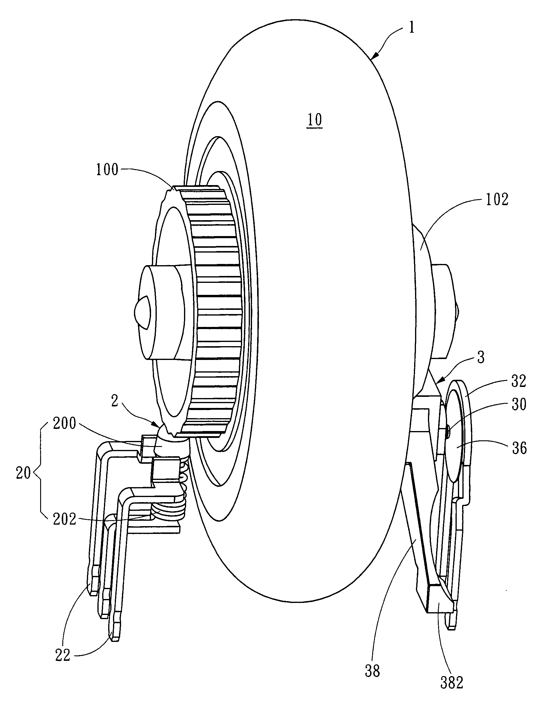
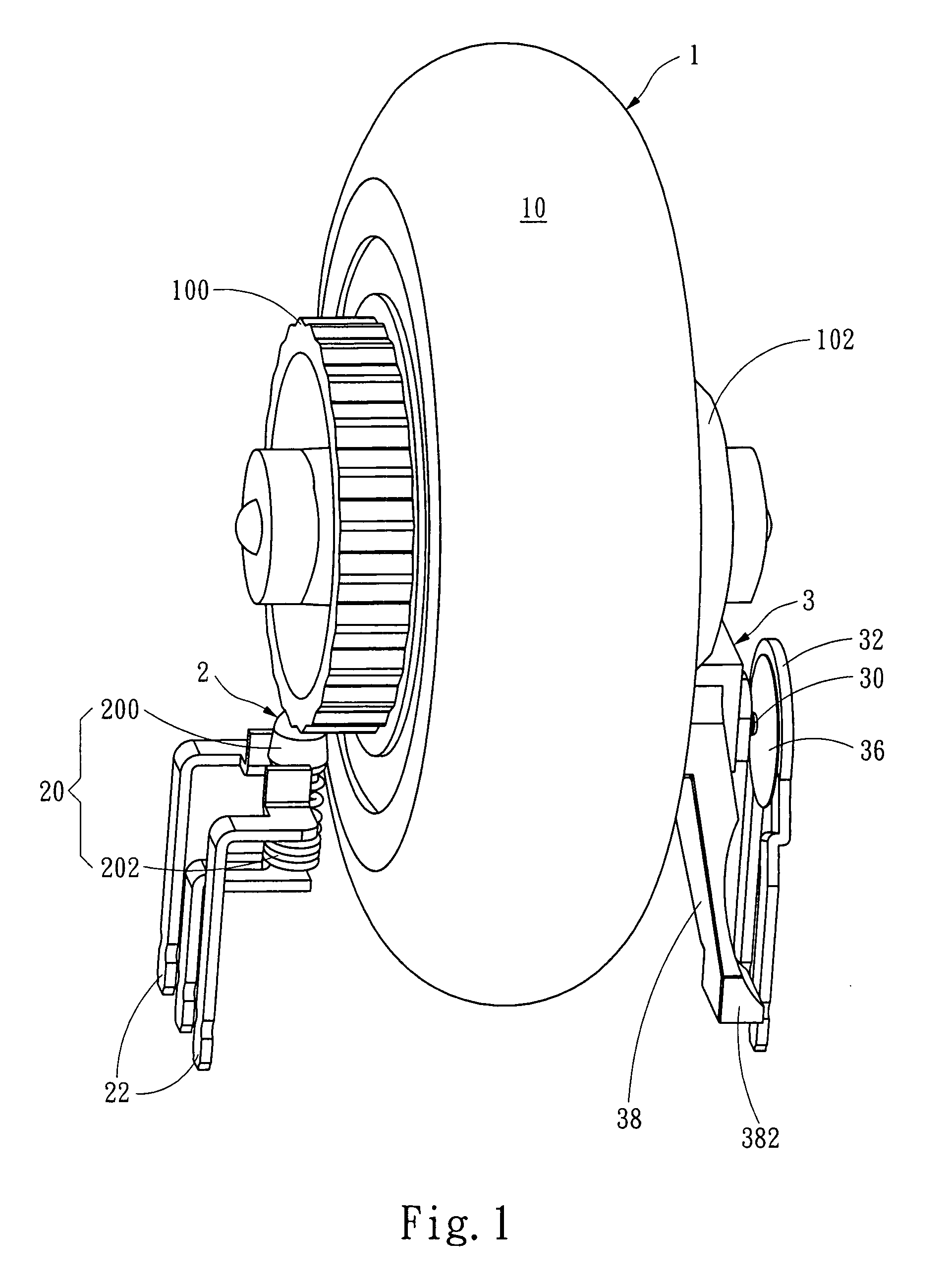
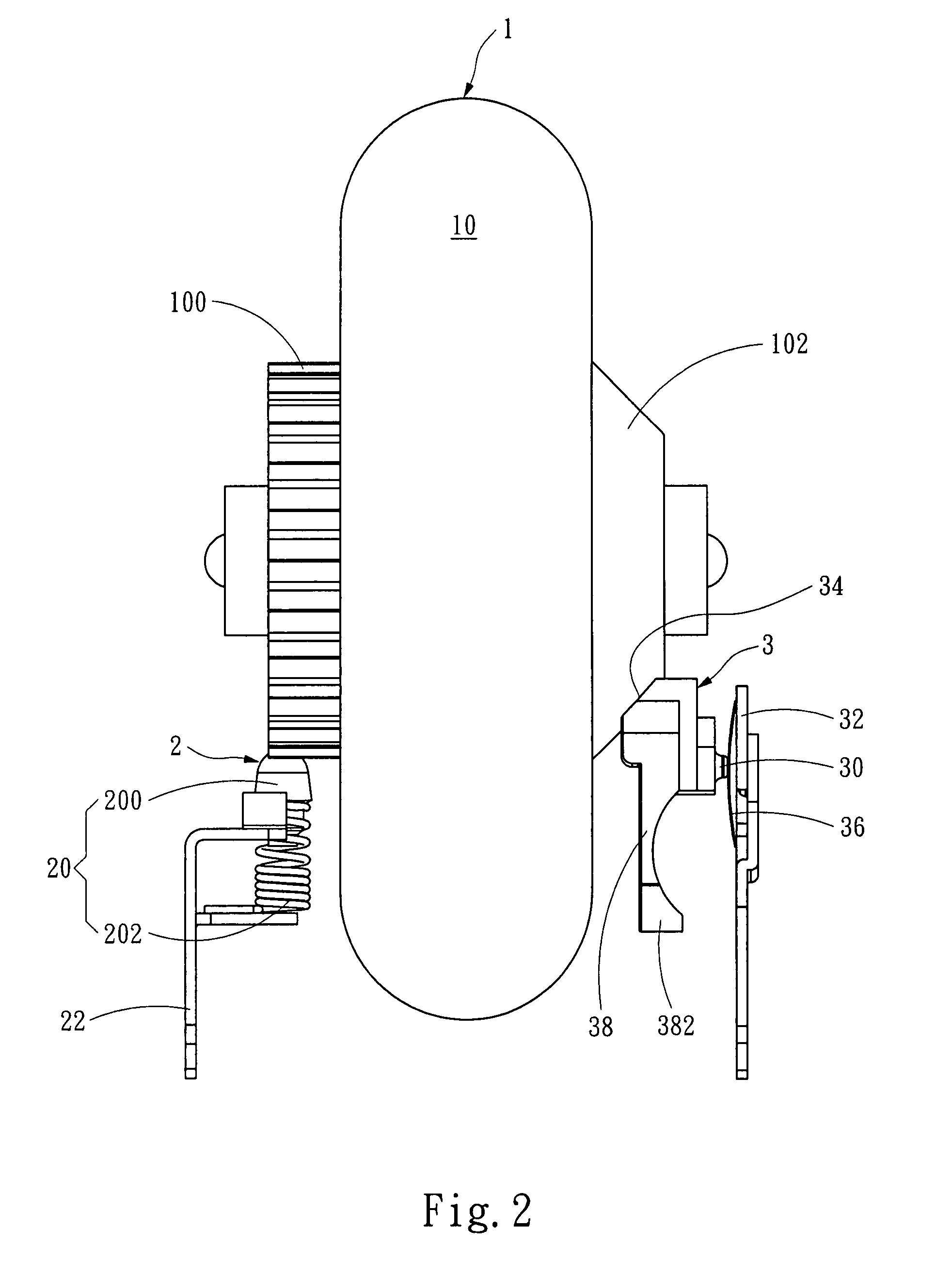
[0015]Refer to FIGS. 1 and 2 for an embodiment of the integrated structure for directional wheel support and signal triggering of the invention. It includes:

[0016]a directional wheel 1 which is depressible downwards and turnable forwards and rearwards. It has a roller 10 movable under a force. The roller 10 has a left side forming a first leaning portion 100 and a right side forming a second leaning portion 102. In this embodiment the first leaning portion 100 is a coaxial gear and the second leaning portion 102 is a coaxial annular sloped surface;

[0017]a first support structure 2 (also referring to FIGS. 3A, 3B and 3C) which holds the first leaning portion 100 and has at least one first moving end 20 movable by the first leaning portion 100. There is a first contact 22 located within the moving range A1 and A2 of the first moving end 20 to be triggered by the first moving end 20 to generate a first signal. In this embodiment the first moving end 20 is conductive and elastic and con...


PUM


Abstract

The present invention includes a directional wheel which has a roller movable under a force. The roller has two sides forming a first and a second leaning portions that are held by a first and a second support structures. The first support structure and the second support structure have respectively a first moving end and a second moving end movable by the first leaning portion and the second leaning portion. A first contact and a second contact are provided respectively in the moving range of the first and second moving ends to connect the first and second moving ends to generate signals. The first and second leaning portions keep two sides of the direction wheel in a balanced manner in regular conditions. The directional wheel is movable under a force to synchronously move the first and second support structures in the direction of the force to generate a corresponding signal.

Description

FIELD OF THE INVENTION[0001]The present invention relates to an integrated structure and particularly to an integrated structure to support a direction wheel and trigger signals.BACKGROUND OF THE INVENTION[0002]Computer input devices using a roller such as mice or keyboards are known in the art. U.S. Pat. No. 6,700,564 B2 granted to Microsoft Co. and U.S. patent publication No. 2003 / 0025673 A1 disclose an input device which has a roller to allow users to turn the roller with fingers to change pages, scroll text or edit text of documents during browsing the documents on a computer screen. It is especially convenient for the users to browse the documents, search Web pages or zoom / shrink images and skip pages or lines without striking the page down / up keys on the keyboard, or maneuvering the scroll bar on the browsing window through a mouse.[0003]However the conventional roller device is complicated and bulky. Fabrication and assembly are difficult. Manufacturing cost is higher. To shr...

Claims


Application Information

Patent Timeline
Patent Type & Authority Applications(United States)
IPC IPC(8): G06F3/033
CPCG06F3/0362
Inventor CHOU, CHIN-WEN
Owner ZIPPY TECH
Why Eureka
Try Eureka