Projector and brightness adjusting method

a technology of brightness adjustment and projector, which is applied in the field of projector and brightness adjustment method, can solve the problems of user discomfort, user discomfort, and the effect of comforting us

Inactive Publication Date: 2009-01-15
SEIKO EPSON CORP
View PDF8 Cites 5 Cited by
  • Summary
  • Abstract
  • Description
  • Claims
  • Application Information

AI Technical Summary

Benefits of technology

[0009]An advantage of some aspects of the invention is that it provides a projector, which can be comfortably used by a user in a case where a projector body and an image output device are in a relative rotation operation state or a recording medium is in an insertion or ejection operation state, and a brightness adjusting method.

Problems solved by technology

However, in the case of the projector disclosed in JP-A-2005-99617, there is a problem that light emitted from the projection lens may strike upon a user when the projecting section is made to rotate relative to the DVD reproduction section, and as a result, the user may feel uncomfortable.
Accordingly, there is a problem that the light emitted from the projection lens may strike upon the user, and as a result, the user may feel uncomfortable.

Method used


Image

  • Projector and brightness adjusting method
  • Projector and brightness adjusting method
  • Projector and brightness adjusting method

Examples


first embodiment

[0034]Hereinafter, an embodiment of the invention will be described with reference to the accompanying drawings.

Schematic Configuration of a Projector

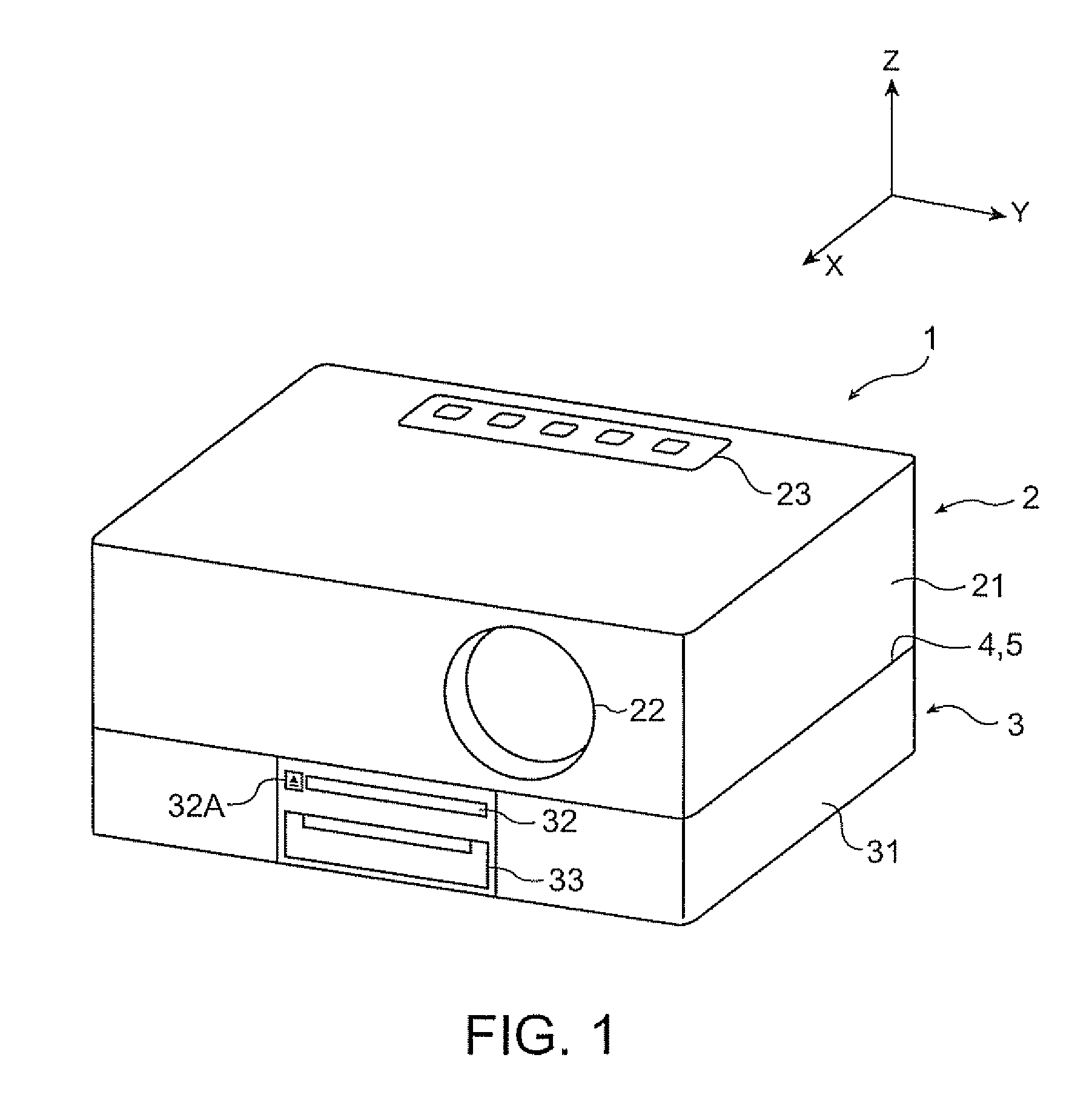
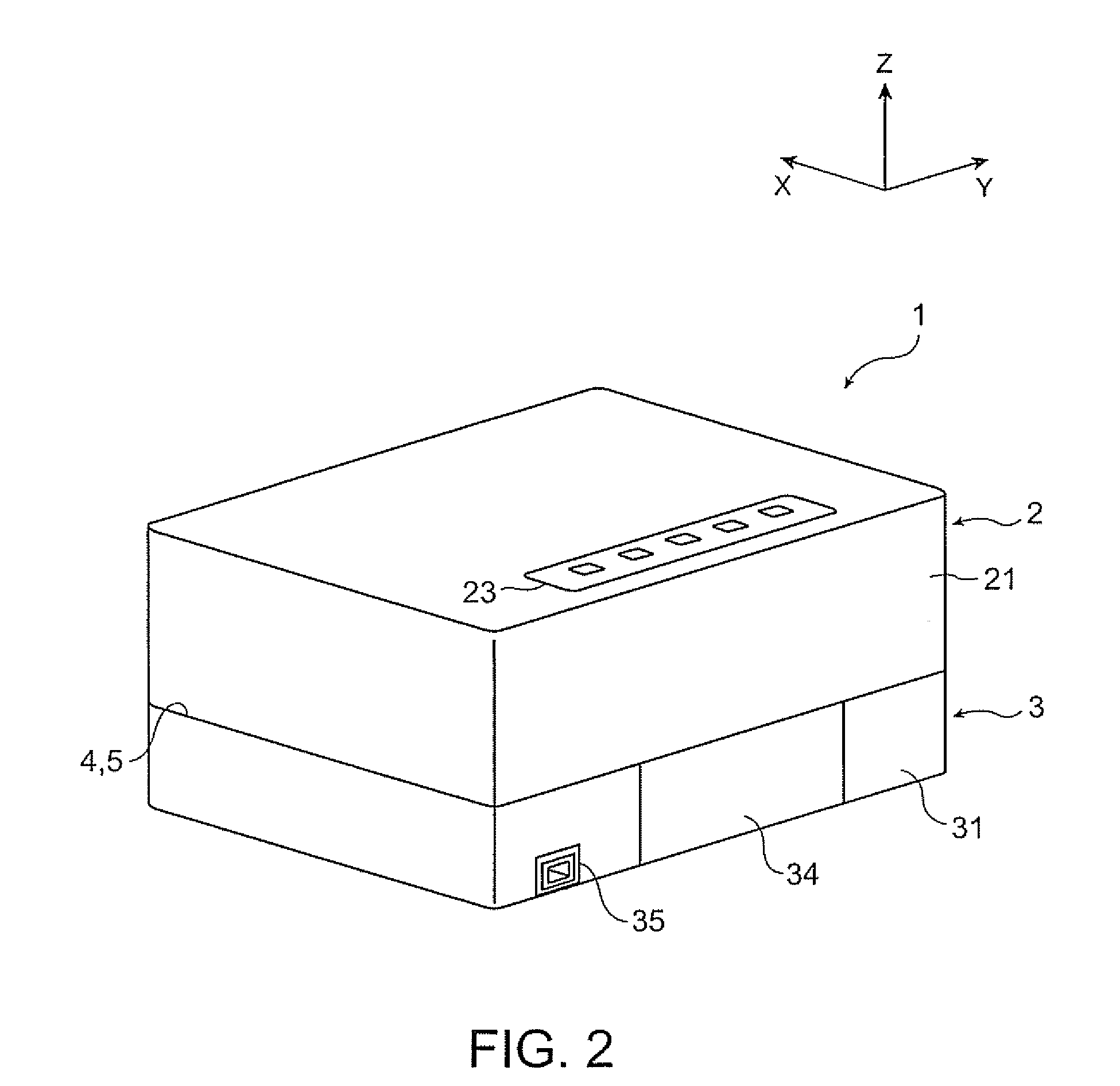
[0035]FIG. 1 is a perspective view illustrating a projector 1 as viewed from a front side, and FIG. 2 is a perspective view illustrating the projector 1 as viewed from a rear side. FIG. 3 is an exploded perspective view illustrating the projector 1 as viewed from the front side. Moreover in FIGS. 1 to 3, the direction from the rear side of the projector 1 to the front side thereof is set to an X axis and two axes perpendicular to the X axis are set to a Y axis (horizontal axis) and a Z axis (vertical axes), respectively, for the convenience of explanation. The same is true for the following drawings.

[0036]As shown in FIGS. 1 to 3, the projector 1 includes: a projector body 2 that forms an optical image by modulating light emitted from a light source according to input image information and projects the formed optical image in an enlarg...

second embodiment

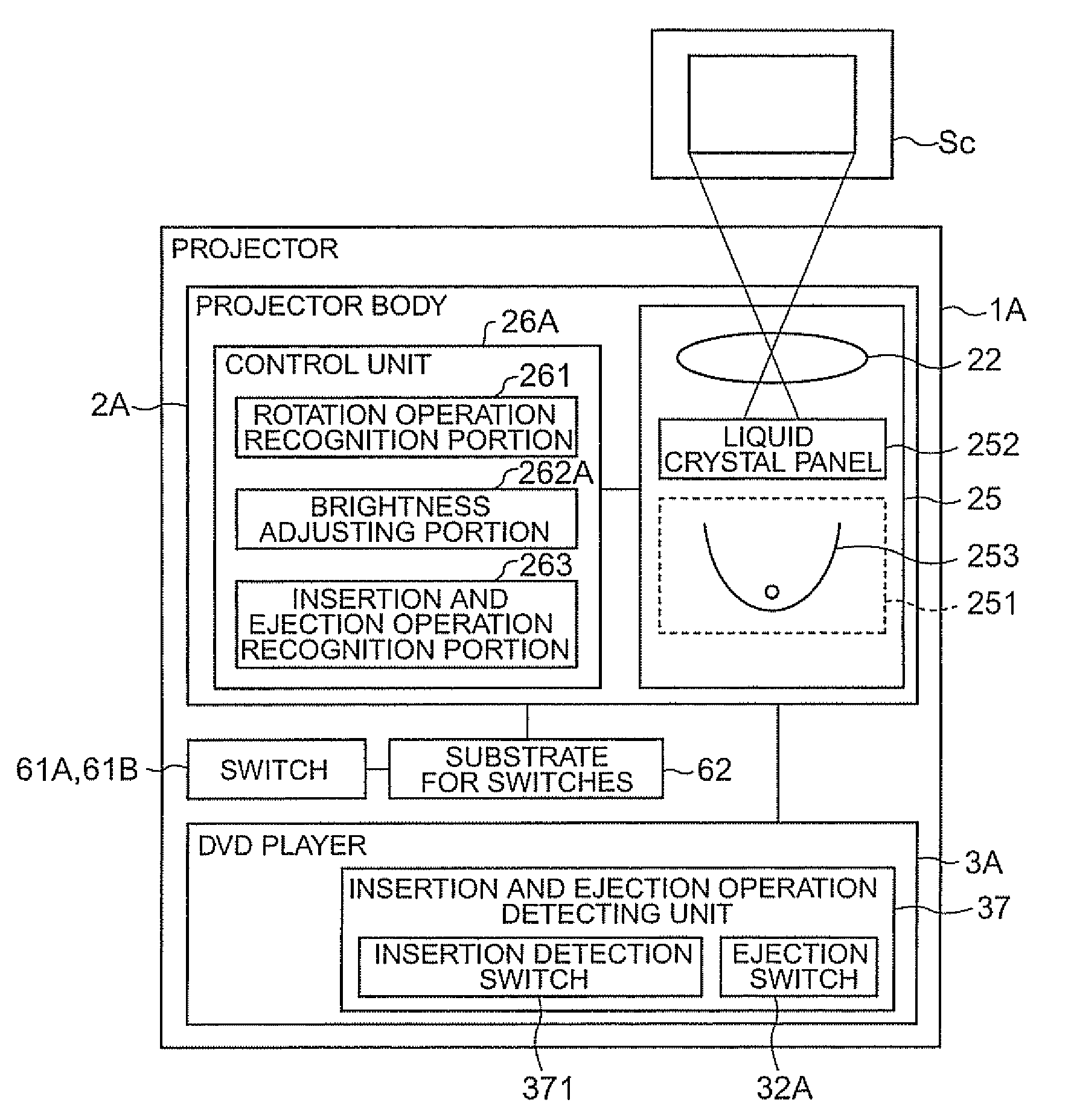
[0085]Hereinafter, a projector 1A according to a second embodiment of the invention will be described.

[0086]Moreover, in the following description, components that have been already described are denoted by the same reference numerals, and a detailed explanation thereof will be omitted.

[0087]In the projector 1 according to the first embodiment, the brightness adjusting portion 262 adjusts the brightness of light emitted from the projection lens 22 when the rotation operation recognition portion 261 has recognized that the projector body 2 and the DVD player 3 are in the relative rotation operation state. However, the projector 1A according to the present embodiment is different from the projector 1 according to the first embodiment in that an insertion and ejection operation recognition portion 263 for recognizing whether or not a recording medium is in an insertion or ejection operation state is included and a brightness adjusting portion 262A adjusts the brightness of light emitte...


PUM


Abstract

A projector includes: a projector body, which has a light modulating device that modulates light emitted from a light source according to input image information to thereby form an optical image and a projection optical device that projects the formed optical image in an enlarged manner; an image output device that outputs the image information to the projector body; a connection mechanism for connecting the projector body and the image output device with each other such that the projector body and the image output device can rotate relative to each other; a rotation operation detecting unit that detects a relative rotation operation of the projector body and the image output device; and a control unit that controls the projector body and the rotation operation detecting unit. The control unit includes: a rotation operation recognition portion that recognizes whether or not the projector body and the image output device are in a relative rotation operation state on the basis of a detection result of the rotation operation detecting unit; and a brightness adjusting portion that adjusts the brightness of light emitted from the projection optical device when the rotation operation recognition portion has recognized that the projector body and the image output device are in the relative rotation operation state.

Description

[0001]This application claims priority from Japanese Patent Application No. 2007-184687 filed in the Japanese Patent Office on Jul. 13, 2007, the entire disclosure of which is hereby incorporated by reference in its entirety.BACKGROUND[0002]1. Technical Field[0003]The present invention relates to a projector and a brightness adjusting method.[0004]2. Related Art[0005]There is known a projector that includes a projector body, which has a light modulating device that modulates light emitted from a light source according to input image information to thereby form an optical image and a projection optical device that projects the formed optical image in an enlarged manner, and an image output device that outputs the image information to the projector body, the projector body and the image output device being configured to be able to rotate relative to each other (for example, refer to JP-A-2005-99617).[0006]The projector disclosed in JP-A-2005-99617 is configured such that a projecting ...

Claims


Application Information

Patent Timeline
Patent Type & Authority Applications(United States)
IPC IPC(8): G03B21/20
CPCG03B29/00G03B21/14G03B21/145H04N5/74
Inventor IGARASHI, MITSUHIKOMATSUMOTO, MORIOYAMAMOTO, KAZUMI
Owner SEIKO EPSON CORP
Why Eureka
Try Eureka