Broad beam light

a broad beam and light technology, applied in semiconductor devices, lighting and heating apparatus, light source applications, etc., can solve the problems of easy failure to meet specifications, lighting devices emitted by non-uniform light beams require excessive power, and lighting devices with central zones of depressed intensity are usually not desirable for many applications, so as to increase the intensity of the adjacent zone.

Active Publication Date: 2009-01-15
MCDERMOTT MARY JANE
View PDF11 Cites 16 Cited by
  • Summary
  • Abstract
  • Description
  • Claims
  • Application Information

AI Technical Summary

Problems solved by technology

A lighting device which emits a light beam having a central zone of depressed intensity is usually not desirable for many applications.
In addition it can easily fail to meet specifications that require a centrally located peak intensity.
This change in the prior art design results in an emerging beam pattern of light concentrated by lens 1 emitted by each LED which would appear to be problematic for many applications.
However, it is especially problematic for specifications which require a peak intensity at the center of the projected beam.
This objective is universal because lighting devices which emit non-uniform light beams require excessive power.
Therefore, changes in prior art designs which could encourage azimuthal variations in the intensity of the emerging beam would normally be considered as problematic.
Prior art additionally discloses problems relating to the shape of the LED lamp that is used.
This concept does minimize enlargement of the LED source but—due to manufacturing variations in the spherical contour and placement of the LED element—does not totally eliminate it.
Nevertheless, this type of problem is one reason that prior art places its LED arrays at a substantial focal distance (visually observed from the figures provided in the referenced prior art) from the lens.
Unfortunately, the large focal length indicated by referenced prior art when combined with the plurality of LED emitters employed to assure an azimuthally uniform beam work against designing a lighting device which is compact, efficient and emitting light having a broad beam spread.
The first was overcoming possible enlargement of the apparent point of emission resulting from the limited number of commercially available LED packages both bright enough to meet intensity requirements and devoid of domes or lenses.
However, as the permissible vertical beam spread of the composite elongated light beam is broadened, the loss in efficiency due to a reduced focal length is reduced.

Method used


Image

  • Broad beam light
  • Broad beam light
  • Broad beam light

Examples


Embodiment Construction

FIGS. 1-12

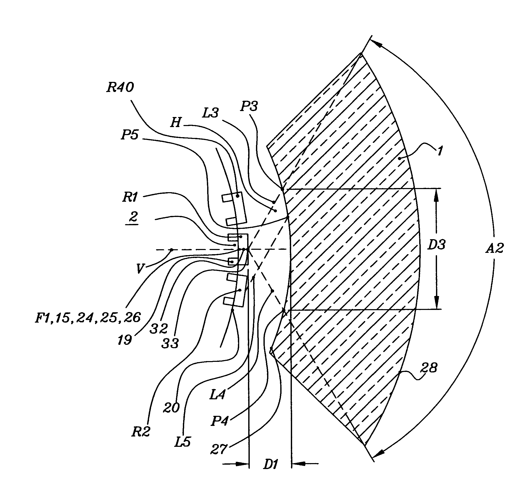
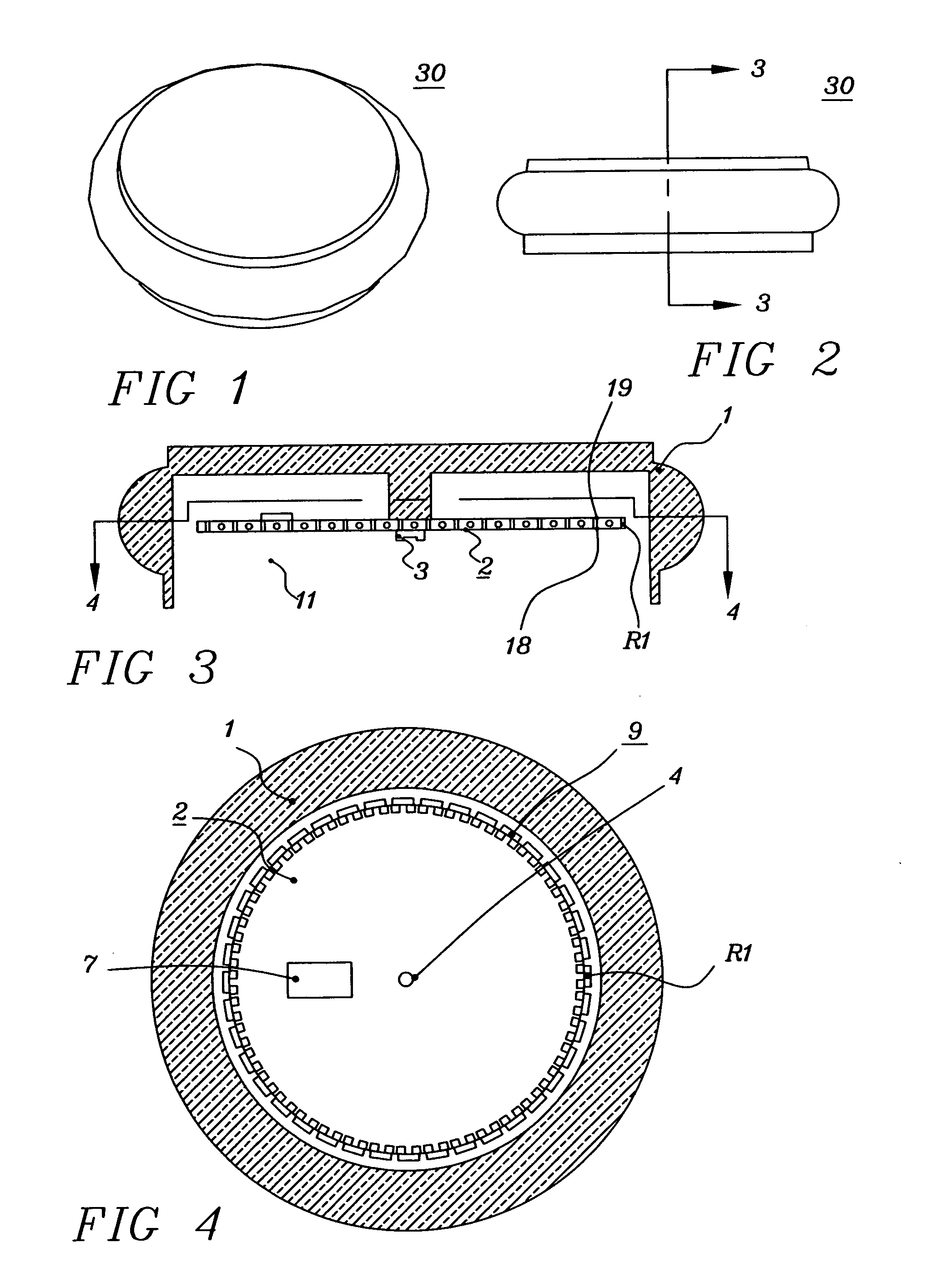
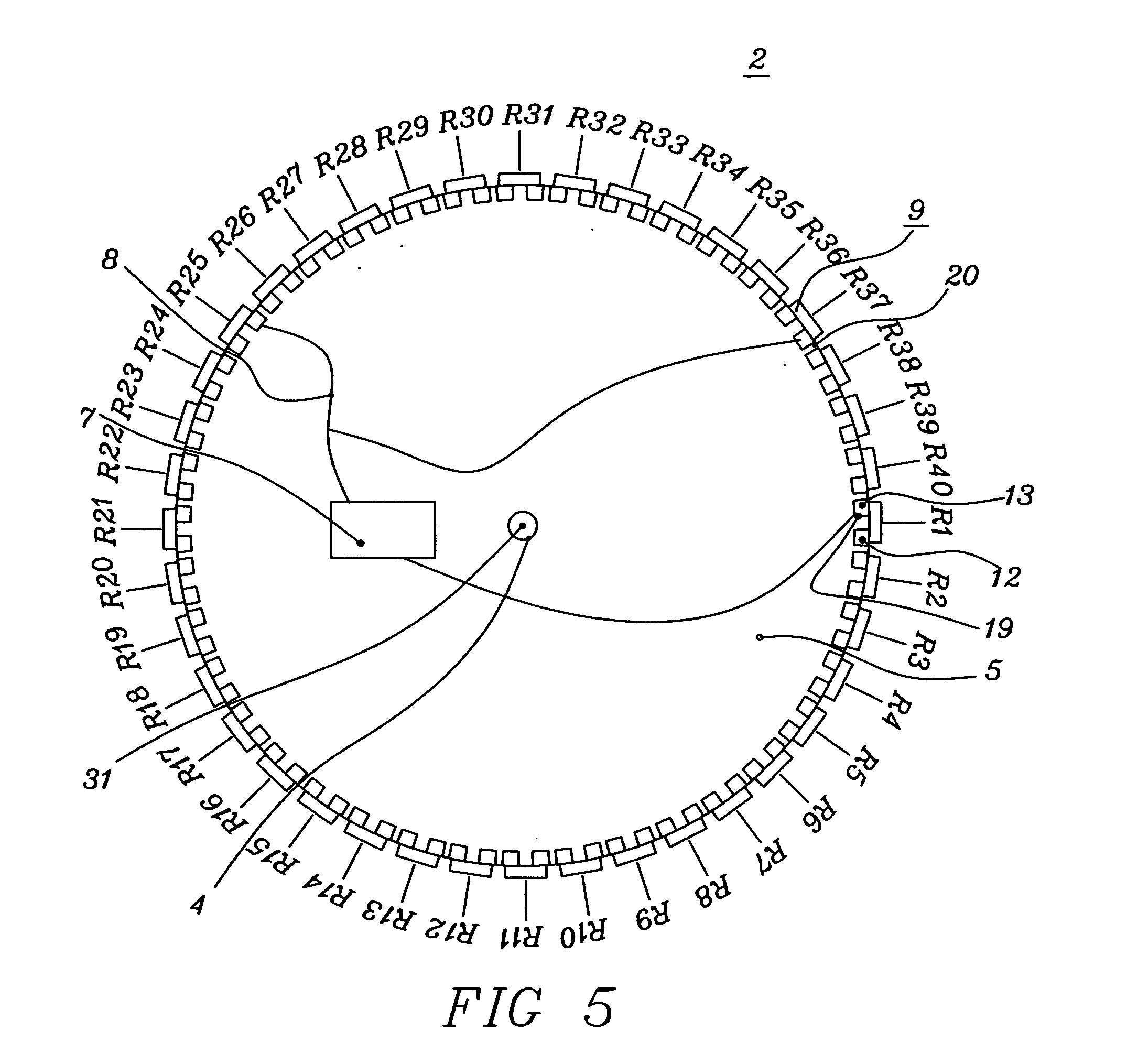
[0070]Lighting device 30 of FIGS. 1 through 14 is the preferred embodiment of the present invention. Lighting device 30 is a device in which a plurality of LED lamps emit light which is intensified and emitted through a single lens to form a broad beam elongated light beam having a minimum intensity throughout a vertical beam spread of ten degrees from minus five degrees to plus five degrees throughout a three hundred and sixty degree azimuth. There are a large number of user defined required specifications. Some require a peak intensity at the center of the beam and define a beam angle as the included angle between directions at which the intensity has decreased to an established percentage—usually 10 or 50—of the peak intensity. Other common specifications require light beams having vertical beam spreads of ten and thirteen degrees elongated to illuminate a three hundred and sixty degree azimuth. In order to comply with a particular specification, adjustments in the desi...


PUM


Abstract

A high efficiency, broad beam lighting device 30 having a converging lens 1 having a curved focal line 26. A source of light comprising a plurality 9 of ceramic LED lamps disposed in an equiangular array having their apparent emission line between minimum divergence curved line 37 and interior surface 27 of converging lens 1 on broad beam curved line 39 such that each LED has its emitted light concentrated by lens 1 into an elongated light beam comprising a central zone substantially surrounded by a peripheral zone. Converging lens 1 further concentrates the light emitted by plurality 9 of LED lamps into a composite elongated light beam having a broad vertical beam spread and concurrently increasing the intensity at the location of the central zone of the elongated light beam of each LED by adding to that central zone location light from the elongated light beam of at least one adjacent LED.

Description

BACKGROUND OF THE INVENTION[0001]1. Field of Invention[0002]This invention relates to a high efficiency, broad beam lighting device which employs as a light source a plurality of LED lamps disposed within a hollow of a converging lens. Each LED lamp emitting light concentrated by the converging lens to form an elongated light beam whereby the elongated light beams overlap such that the light at a central zone of one elongated light beam is bolstered by light extending into that central zone from an adjacent elongated light beam to form a composite elongated light beam having a specification azimuth and specification broad vertical beam spread.[0003]2. Prior Art[0004]Prior art developed designs which either maximized the intensity directly in front of each LED lamps of a plurality of LED lamps in the horizontal direction or minimized the divergence of the composite light beam about the horizontal. These two objectives are very similar but due to the fact that the converging lens is f...

Claims


Application Information

Patent Timeline
Patent Type & Authority Applications(United States)
IPC IPC(8): F21V3/02
CPCF21V5/046F21Y2101/02F21W2111/00F21Y2115/10
Inventor MCDERMOTT, KEVIN
Owner MCDERMOTT MARY JANE
Why Eureka
Try Eureka