
Multiple level cell phase-change memory devices having post-programming operation resistance drift saturation, memory systems employing such devices and methods of reading memory devices

a phase-change memory and phase-change technology, applied in the field of memory systems employing such devices, can solve the problems of difficult to address resistance drift, and achieve the effect of preventing or greatly minimizing the resistance drift of phase-change materials

Active Publication Date: 2009-01-15
SAMSUNG ELECTRONICS CO LTD
View PDF59 Cites 19 Cited by
  • Summary
  • Abstract
  • Description
  • Claims
  • Application Information

AI Technical Summary

Benefits of technology

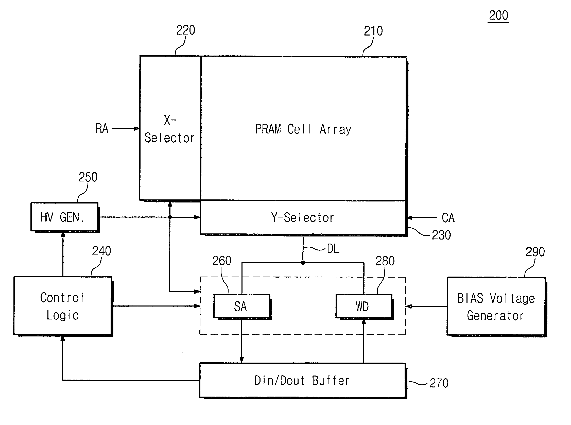
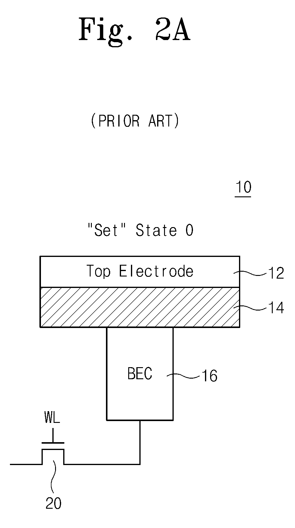
[0017]Embodiments of the present invention are directed to multiple level cell phase-change memory devices, memory systems employing such devices and methods of reading memory devices, wherein resistance drift of a memory cell of the memory device is controlled by applying a saturation pulse of heating current to the memory cell following a writing operation of the cell. The saturation pulse operates to prevent, or greatly minimize, further resistance drift in the phase change material of the programmable volume of the memory cell over time. In one example, a saturation heating pulse is applied to the cell within a time period, for example, within less than about 1 μs of the programming pulse used to write data to the cell. Such heating of the cell following the write operation accelerates, or saturates, the resistance drift of the cell, so that little or no further resistance drift of the cell will occur.

Problems solved by technology

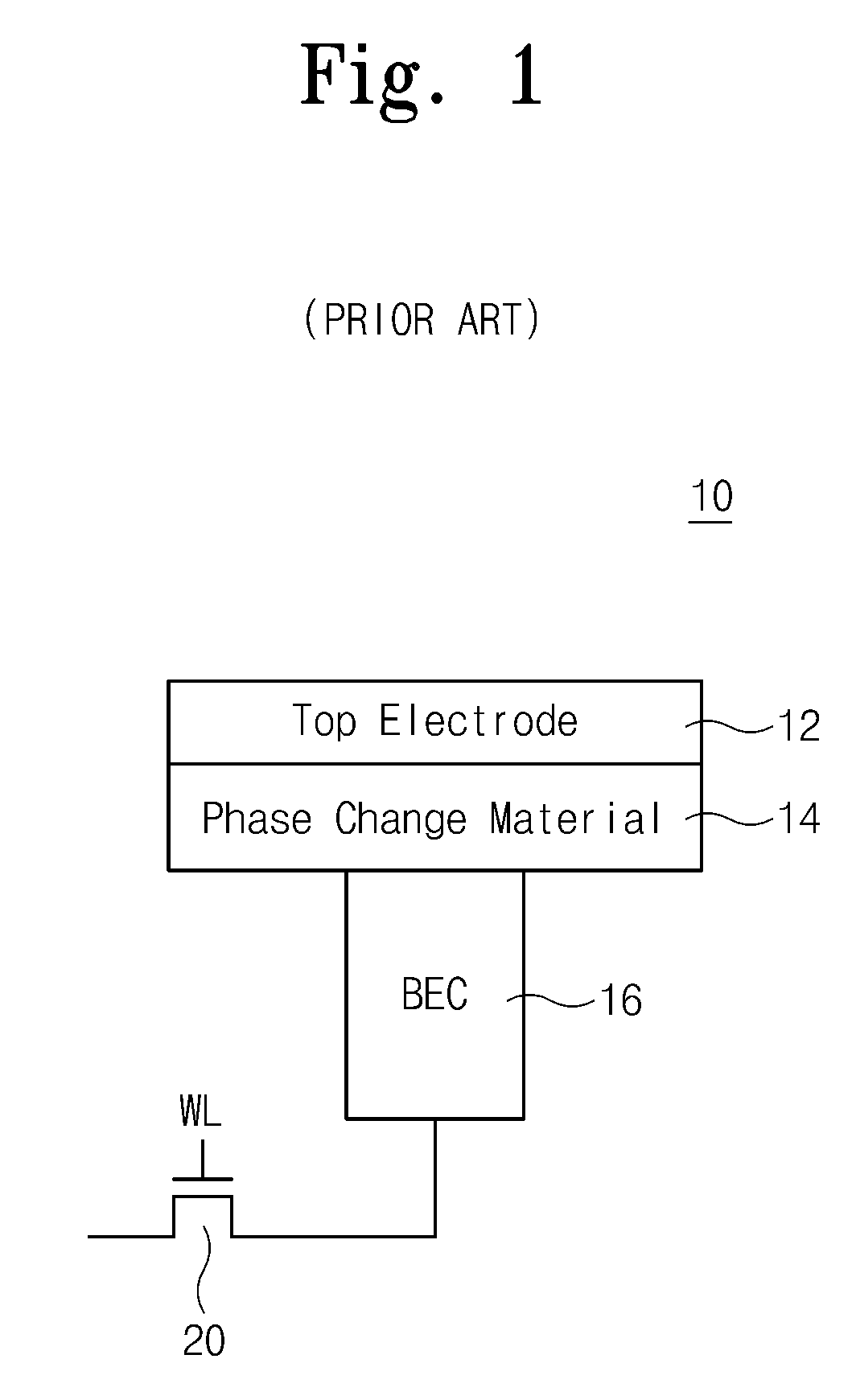
However, resistance drift remains a difficult problem to address, especially in multiple-level PRAM devices.

Method used


Image

  • Multiple level cell phase-change memory devices having post-programming operation resistance drift saturation, memory systems employing such devices and methods of reading memory devices
  • Multiple level cell phase-change memory devices having post-programming operation resistance drift saturation, memory systems employing such devices and methods of reading memory devices
  • Multiple level cell phase-change memory devices having post-programming operation resistance drift saturation, memory systems employing such devices and methods of reading memory devices

Examples


Embodiment Construction

[0067]Embodiments of the present invention will now be described more fully hereinafter with reference to the accompanying drawings, in which preferred embodiments of the invention are shown. The invention may, however, be embodied in different forms and should not be construed as limited to the embodiments set forth herein. Like numbers refer to like elements throughout the specification.

[0068]It will be understood that, although the terms first, second, etc. are used herein to describe various elements, these elements should not be limited by these terms. These terms are used to distinguish one element from another. For example, a first element could be termed a second element, and, similarly, a second element could be termed a first element, without departing from the scope of the present invention. As used herein, the term “and / or” includes any and all combinations of one or more of the associated listed items.

[0069]It will be understood that when an element is referred to as be...


PUM


Abstract

In a memory device and in a method of programming the same, a memory device comprises: a plurality of memory cells, each memory cell comprising a resistance-changeable material that has an initial resistance that is determined in response to an applied programming current in a programming operation; and a modification circuit that modifies the resistance of the memory cell following a programming operation of the memory cell to vary the resistance of the memory cell from the initial resistance to a second resistance by applying a saturation current in a saturation operation. Each memory cell is connected to a conduction line of the memory device that is used to apply the programming current to program the resistance of the corresponding memory cell in the programming operation, that is used to apply the saturation current to the corresponding memory cell in the saturation operation and that is used to apply a read current to read the resistance of the corresponding memory cell in a subsequent read operation.

Description

RELATED APPLICATIONS[0001]This application claims priority under 35 U.S.C. 119 to Korean Patent Application No. 10-2007-0070161 filed on Jul. 12, 2007, the content of which is incorporated herein by reference in its entirety.[0002]This application is related to U.S. Ser. No. (our SAM-1115), filed of even date herewith, entitled “Multiple-Level Cell Phase-Change Memory Devices Having Pre-Reading Operation Resistance Drift Recovery, Memory Systems Employing Such Devices, and Methods of Reading Memory Devices,” by Chang-Wook Jeong, et al., and commonly owned with the present application, the content of which is incorporated herein by reference.[0003]This application is related to U.S. Ser. No. (our SAM-1116), filed of even date herewith, entitled “Multiple-Level Cell Phase-Change Memory Devices Having Controlled Resistance Drift Parameter, Memory Systems Employing Such Devices, and Methods of Reading Memory Devices,” by Chang-Wook Jeong, et al., and commonly owned with the present appl...

Claims


Application Information

Patent Timeline
IPC IPC(8): G11C11/00G11C7/00
CPCG11C8/08G11C11/5678G11C13/0004G11C2013/0078G11C13/0038G11C13/0061G11C13/0069G11C13/0028G11C16/04G11C16/30G11C16/34
Inventor JEONG, CHANG-WOOKKANG, DAE-HWANKIM, HYEONG-JUNSHIN, JAE-MINKO, SEUNG-PIL
Owner SAMSUNG ELECTRONICS CO LTD
Learn More