Airflow Reducing and Redirecting Arrangement For Industrial Baghouse

a technology for airflow reduction and airflow redirection, which is applied in the direction of auxillary pretreatment, separation process, dispersed particle separation, etc., can solve the problems of complex operation parameters, reduced gas flow rate through filter media, and increased pressure drop across filter media, so as to reduce the flow velocity of the effect of introducing the gas stream of a particulate bearing

Inactive Publication Date: 2009-01-22
MENARDI MIKROPUL LLC
View PDF19 Cites 27 Cited by
  • Summary
  • Abstract
  • Description
  • Claims
  • Application Information

AI Technical Summary

Benefits of technology

[0010]As a first aspect, embodiments of the present invention are directed to an air filtering unit for a factory. The air filtering unit comprises: an entry duct; a flow expander section fluidly connected with the entry duct, the flow expander section including a flow distribution unit and a flow velocity reduction unit; a filter unit fluidly connected with the flow expander section, the filter unit having a plurality of filter bags, the filter bags being suspended from a tube sheet; and an exit duct fluidly connected with the filter unit. The flow distribution unit comprises a series of flow distribution members positioned along a flow path, the flow distribution unit located and configured to substantially equally distribute an airstream along the length of the flow axis into a plurality of divided substreams. The flow velocity reduction unit includes a plurality of flow reduction members, each of the flow reduction members positioned and configured to confront at least one of the divided substreams and reduce the flow velocity thereof. In this configuration, the filter unit may be more efficient in removing particulate matter from the dirty airstream.

Problems solved by technology

The particulate matter borne by the incoming gas stream normally accumulates on the outer surface of the bag and, unless removed by dislodgement, results in a progressive increase in pressure drop across the filter media and in a concomitant reduction in the rate of gas flow through the filter media.
In addition to the foregoing, achieving optimum operating parameters for the introduction of a particulate bearing gas stream into a dust collector is often complicated, if not effectively precluded, by physical restraints at the installation site.
Among such physical restraints may be a less than adequate area for installation, the presence of duct work, piping, support columns, walls, catwalks and other impediments to ideal installation conditions.
The transition of the shape and velocity of the incoming particulate bearing gas stream to the desirable flow conditions within the fabric filter media housing has been a long-standing problem in this field.
While most of such expedients have resulted in some degree of improved performance, the net results have fallen far short of optimum and the problem of achieving high efficiency and economic operation of industrial fabric filter dust collectors remains a continuing one.

Method used


Image

  • Airflow Reducing and Redirecting Arrangement For Industrial Baghouse
  • Airflow Reducing and Redirecting Arrangement For Industrial Baghouse
  • Airflow Reducing and Redirecting Arrangement For Industrial Baghouse

Examples


Embodiment Construction

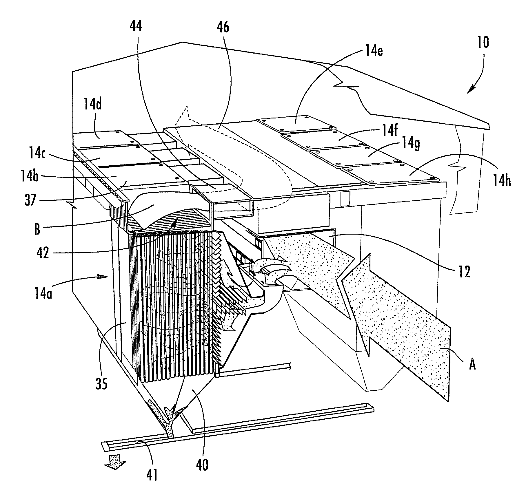
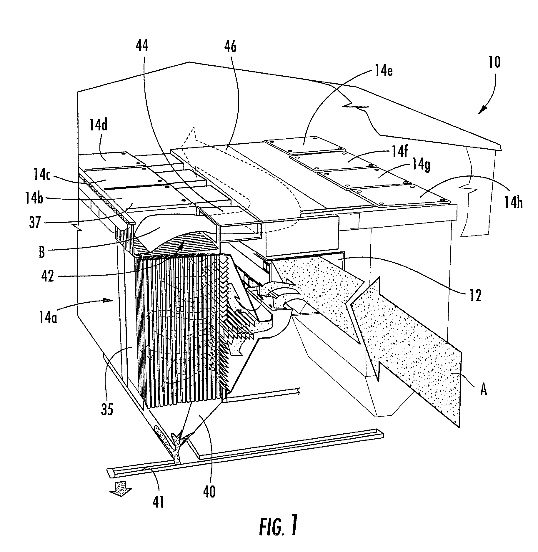
[0015]The present invention will now be described more fully hereinafter, in which preferred embodiments of the invention are shown. This invention may, however, be embodied in different forms and should not be construed as limited to the embodiments set forth herein. Rather, these embodiments are provided so that this disclosure will be thorough and complete, and will fully convey the scope of the invention to those skilled in the art. In the drawings, like numbers refer to like elements throughout. Thicknesses and dimensions of some components may be exaggerated for clarity.

[0016]Unless otherwise defined, all terms (including technical and scientific terms) used herein have the same meaning as commonly understood by one of ordinary skill in the art to which this invention belongs. It will be further understood that terms, such as those defined in commonly used dictionaries, should be interpreted as having a meaning that is consistent with their meaning in the context of the releva...


PUM

PropertyMeasurementUnit
velocityaaaaaaaaaa
velocityaaaaaaaaaa
velocityaaaaaaaaaa

Abstract

An air filtering unit for a factory includes: an entry duct; a flow expander section fluidly connected with the entry duct, the flow expander section including a flow distribution unit and a flow velocity reduction unit; a filter unit fluidly connected with the flow expander section, the filter unit having a plurality of filter bags, the filter bags being suspended from a tube sheet; and an exit duct fluidly connected with the filter unit. The flow distribution unit comprises a series of flow distribution members positioned along a flow path, the flow distribution unit located and configured to substantially equally distribute an airstream along the length of the flow axis into a plurality of divided substreams. The flow velocity reduction unit includes a plurality of flow reduction members, each of the flow reduction members positioned and configured to confront at least one of the divided substreams and reduce the flow velocity thereof.

Description

RELATED APPLICATION[0001]This application claims the benefit of U.S. Provisional Patent Application No. 60 / 950,682, filed Jul. 19, 2007 in the U.S. Patent and Trademark Office, the disclosure of which is incorporated herein in its entirety by reference.FIELD OF THE INVENTION [0002]This invention relates generally to apparatus for filtering a gas stream, and more particularly to apparatus for filtering the particulates from a gas stream.BACKGROUND OF THE INVENTION [0003]It has long been recognized that control of a gas stream as the gas stream is introduced into a dust collecting apparatus can materially contribute to increased efficiency of operation and extended operating life of the gas treating components thereof. One area of preferential concern has been in the industrial gas filtration field, and particularly in the fabric filter dust collector field. One type of such fabric filter dust collector, also called a “baghouse”, typically employs a large number of tubular fabric filt...

Claims


Application Information

Patent Timeline
Patent Type & Authority Applications(United States)
IPC IPC(8): B01D46/02B01D46/42
CPCB01D46/0043B01D50/002B01D46/02B01D50/20
Inventor GREGG, WILLIAM W.
Owner MENARDI MIKROPUL LLC
Why Eureka
Try Eureka