Attachment of a bridge band to an oxygen mask

Inactive Publication Date: 2009-01-22
LAU GREGORY YUEN FUN
View PDF2 Cites 9 Cited by
  • Summary
  • Abstract
  • Description
  • Claims
  • Application Information

AI Technical Summary

Benefits of technology

[0011]The present invention is directed to an oxygen mask for interfacing a user to the source of a gas with a bridge band to secure and/or se

Problems solved by technology

However, current methods can oftentimes fail, which results in the bridge band

Method used


Image

  • Attachment of a bridge band to an oxygen mask
  • Attachment of a bridge band to an oxygen mask
  • Attachment of a bridge band to an oxygen mask

Examples


Example

[0022]In the following description, terms such as horizontal, upright, vertical above, below, beneath and the like are used solely for the purpose of clarity in illustrating the invention and should not be taken as words of limitation. The drawings are for the purpose of illustrating the invention and are not intended to be to scale.

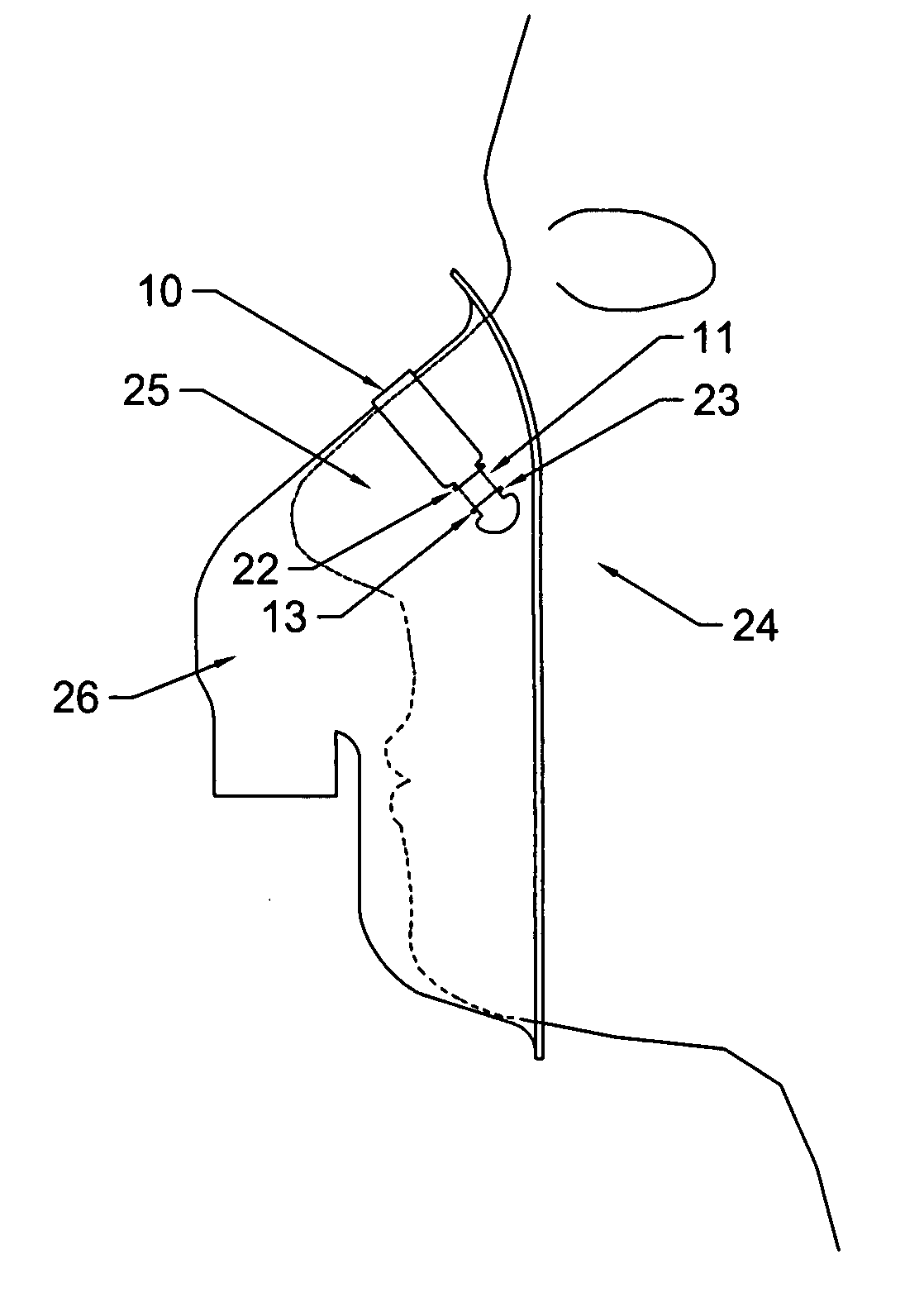
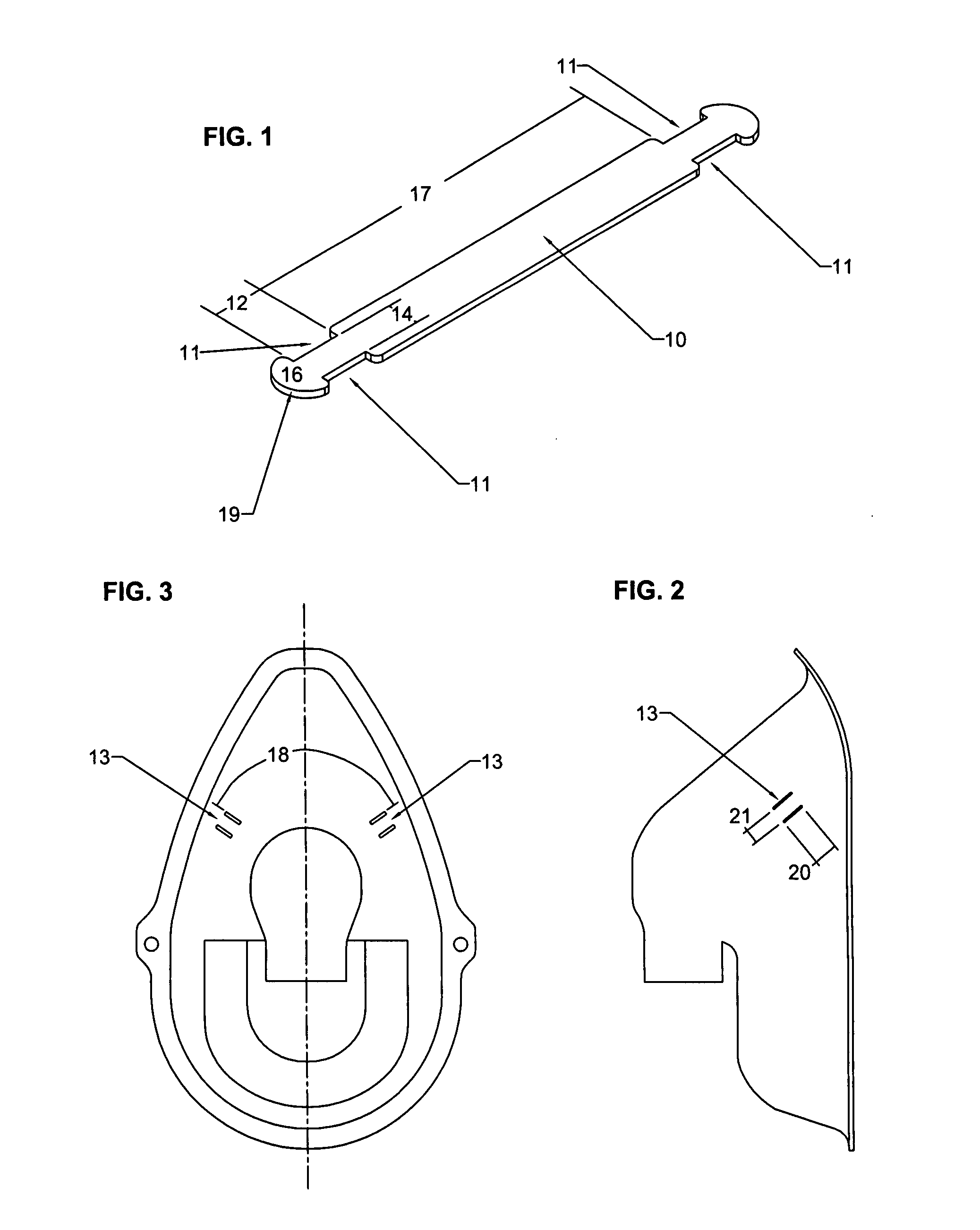
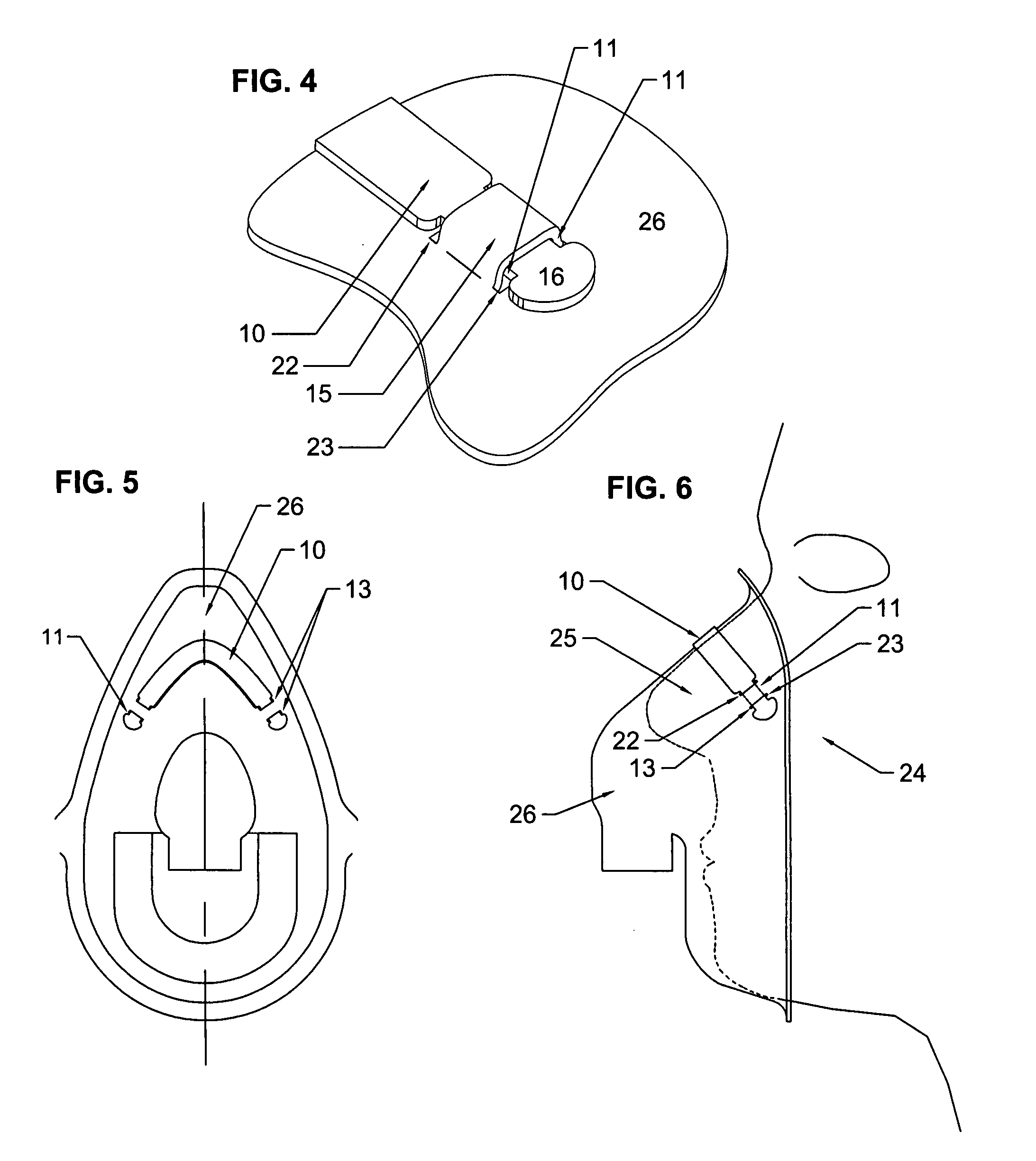
[0023]Referring to the drawings and first to FIG. 1, a bridge band 10 comprising of four recesses 11. The recesses 11 are located towards the ends of the bridge band and are on both sides of the bridge band, making it symmetrical. The recesses' length 12 is such that it can be fully engaged into the openings 13 of FIG. 2. FIG. 4 shows the full engagement between the bridge band and the openings. The width 14 of FIG. 1 created by the opposing recesses is such that a flat barb 16 is created at each end of the bridge band. The distance 17 between the recesses of each end is such that the bridge band will span the contoured distance 18 of FIG. 3 between the ...


PUM


Abstract

The present invention is a method by which a bridge band attaches to an interface used to communicate breathing gases to a user. The bridge band contains two opposing recesses towards each end, which create a neck area. The interface contains openings in the nose area that accepts the recesses of the bridge band. There are two parallel openings on each side of the centerline of the mask. One end of the bridge band is inserted into the first opening and then out of the second opening until the recesses are fully engaged in the openings. Accordingly, the second end is laced through the openings in the same manner on the opposite side of the mask. The openings and recesses are sized appropriately such that they will engage together fully and tightly.

Description

BACKGROUND OF THE INVENTION[0001](1) Field of the Invention[0002]The present invention relates to an oxygen mask used to interface a user to an oxygen delivery system. In particular, the present invention secures a bridge band to the nose area of the mask, which aids in securing the mask to a user's face.[0003](2) Description of the Prior Art[0004]There are certain medical situations in which it is necessary or desirable to deliver a flow of oxygen gas or a mixture of breathing gases to the airway of a patient. Such delivery systems involve the placement of an interface device, which is typically a nasal cannula or mask or tent, on the face of the user. The patient interface device communicates the flow of a gas from the source with the airway of the patient, so that the therapeutic flow of breathing gas can be delivered to the patient's airway.[0005]In a circumstance where a person uses a mask as the interface of this system it is important to be able to secure the mask to the user...

Claims


Application Information

Patent Timeline
IPC IPC(8): A62B18/08
CPCA62B23/025A62B18/084
Inventor LAU, GREGORY YUEN FUN
Owner LAU GREGORY YUEN FUN
Why Eureka
Try Eureka