Contained drive system for chain conveyor belt to reduce catenary sag

Active Publication Date: 2009-01-22
DORNER MFG. CORP.
View PDF22 Cites 14 Cited by
  • Summary
  • Abstract
  • Description
  • Claims
  • Application Information

AI Technical Summary

Benefits of technology

[0007]The present invention generally relates to a conveyor assembly used in connection with a conveyor belt formed from individual link sections, preferably each made from plastic. More particularly, the invention relates to a conveyor assembly that includes an enclosed area within the side frame members that allows the conveyor assembly to compensate for the stretching of the conveyor belt during use of the conveyor belt with a load.
[0008]During use of a conveyor belt under tension, the individual plastic links are pulled, which causes the plastic conveyor belt to stretch and increase in length. Typically, such increase in length is compensated for by a catenary sag in the lower run of the conveyor belt. However, in accordance with the pr

Problems solved by technology

During use of a conveyor belt under tension, the individual plastic links are p

Method used


Image

  • Contained drive system for chain conveyor belt to reduce catenary sag
  • Contained drive system for chain conveyor belt to reduce catenary sag
  • Contained drive system for chain conveyor belt to reduce catenary sag

Examples


Example

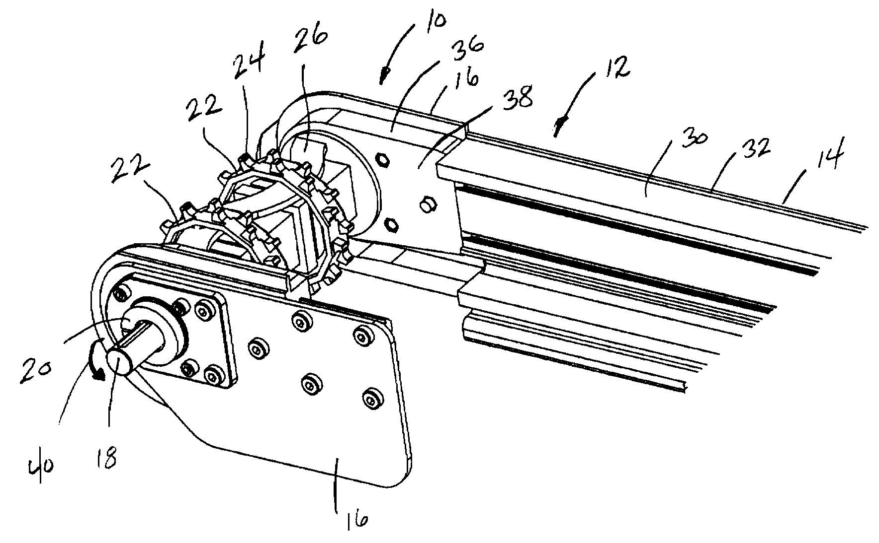
[0016]FIG. 1 illustrates the drive end 10 of a conveyor assembly 12 including a pair of spaced side frame members 14, of which only one is shown in FIG. 1. The drive end 10 includes a pair of spaced side brackets 16 that are each connected to one of the side frame members 14. The side brackets 16 each rotatably support a drive shaft 18 operatively connected to a drive motor (not shown). In the embodiment shown in FIG. 1, the drive shaft 18 is rotatably supported within a bearing assembly 20 contained in each of the side brackets 16. The drive shaft 18 receives a plurality of drive sprockets 22, each of which include a series of spaced teeth 24 that engage the individual links of a conveyor belt. As shown in FIG. 1, a sprocket connector 26 links the series of drive sprockets 22 to provide the desired spacing of the drive sprockets 22 along the length of the drive shaft 18.

[0017]As can best be seen in FIGS. 1 and 5, the side frame member 14 is an extruded aluminum member that includes...


PUM


Abstract

A conveyor frame assembly for use with a conveyor belt formed from individual links each joined together at pivot points. The conveyor frame assembly includes a drive assembly that pulls the conveyor belt around a drive roller to transition between the upper and lower runs of the conveyor belt. The drive end includes a support block that encloses the side edges of the conveyor belt as the conveyor belt transitions over the drive sprockets. The side frame members each include a continuous retaining channel having a height greater than the thickness of the conveyor belt. The retaining channels formed on opposite sides of the conveyor frame assembly allow the lower run of the conveyor belt to “tent” by creating an angle between adjacent links of the conveyor belt assembly. The tenting of the lower run of the conveyor belt eliminates catenary sag.

Description

CROSS-REFERENCE TO RELATED APPLICATION[0001]The present application is based on and claims priority to U.S. Provisional Patent Application Ser. No. 60 / 950,659 filed on Jul. 19, 2007.BACKGROUND OF THE INVENTION[0002]The present invention generally relates to a conveyor frame assembly for use with a plastic chain conveyor belt. More specifically, the present invention relates to a conveyor assembly that reduces the catenary sag of the lower run of the conveyor belt downstream from the drive roller.[0003]In many conveyor applications, a plastic chain conveyor belt is utilized to move materials throughout a facility. The plastic chain conveyor belt includes individual links that run across the width of the conveyor belt such that the conveyor belt can assume a flat transporting condition yet can transition over both a drive roller and an idler roller to create the upper and lower runs of the conveyor belt.[0004]Since plastic chain conveyor belts can be used to move a large number of pro...

Claims


Application Information

Patent Timeline
IPC IPC(8): B65G15/00
CPCB65G21/06B65G21/20B65G21/105
Inventor HOSCH, MICHAEL A.HAU, PAUL
Owner DORNER MFG. CORP.
Why Eureka
Try Eureka