Coil unit and electronic instrument

Active Publication Date: 2009-01-22
SAMSUNG ELECTRONICS CO LTD
View PDF11 Cites 69 Cited by
  • Summary
  • Abstract
  • Description
  • Claims
  • Application Information

AI Technical Summary

Problems solved by technology

Non-contact power transmission has a problem

Method used


Image

  • Coil unit and electronic instrument
  • Coil unit and electronic instrument
  • Coil unit and electronic instrument

Examples


Embodiment Construction

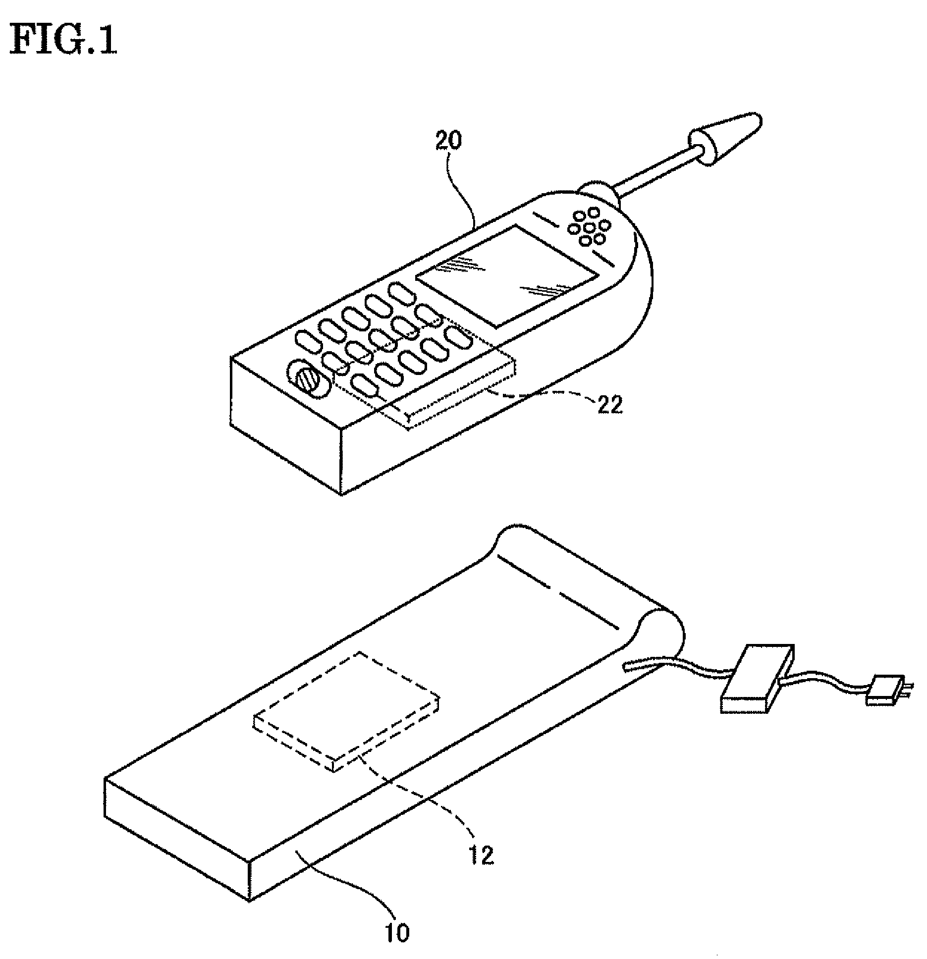
[0023]Several aspects of the invention may provide a coil unit that exhibits excellent heat dissipation capability and can be reduced in thickness, and an electronic instrument using the coil unit.

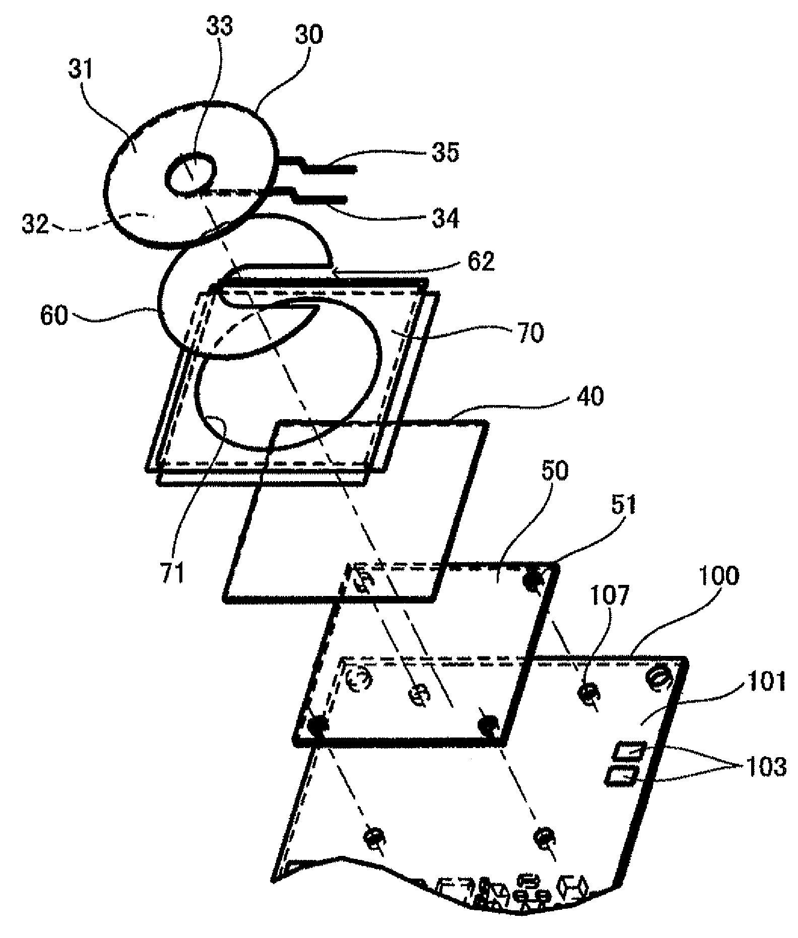
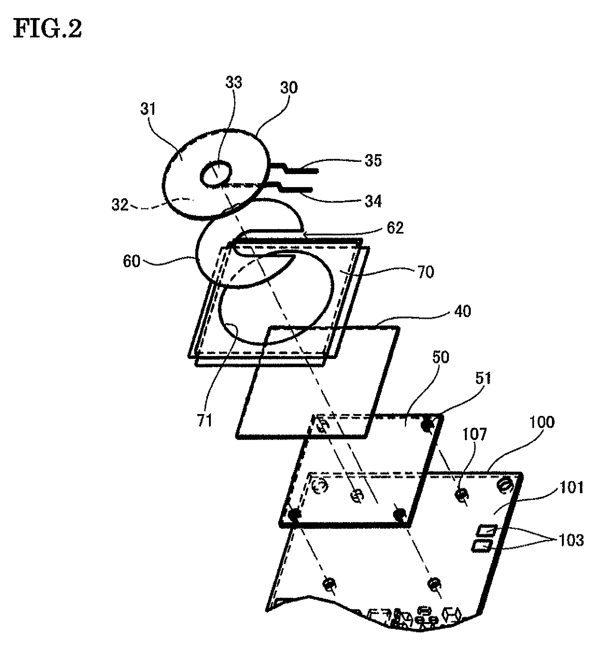
[0024]According to one embodiment of the invention, there is provided a coil unit comprising:

[0025]a planar coil that has a transmission side and a non-transmission side;

[0026]a magnetic sheet provided over the non-transmission side of the planar coil; and

[0027]a heat sink / magnetic shield plate stacked on a side of the magnetic sheet opposite to a side that faces the planar coil, the heat sink / magnetic shield plate dissipating heat generated by the planar coil and shielding magnetism by absorbing a magnetic flux that has not been absorbed by the magnetic sheet,

[0028]the heat sink / magnetic shield plate having a thickness larger than that of the magnetic sheet.

[0029]Heat generated by the planar coil is dissipated through solid heat conduction of the magnetic sheet and the heat sink / magnetic ...


PUM


Abstract

A coil unit includes a planar coil that has a transmission side and a non-transmission side, a magnetic sheet provided over the non-transmission side of the planar coil, and a heat sink/magnetic shield plate stacked on a side of the magnetic sheet opposite to a side that faces the planar coil, the heat sink/magnetic shield plate dissipating heat generated by the planar coil and shielding magnetism by absorbing a magnetic flux that has not been absorbed by the magnetic sheet. The heat sink/magnetic shield plate has a thickness larger than that of the magnetic sheet.

Description

[0001]Japanese Patent Application No. 2007-189812 filed on Jul. 20, 2007, is hereby incorporated by reference in its entirety.BACKGROUND OF THE INVENTION[0002]The present invention relates to a coil unit utilized for non-contact power transmission using a coil, an electronic instrument, and the like.[0003]Non-contact power transmission that utilizes electromagnetic induction to enable power transmission without metal-to-metal contact has been known. As application examples of non-contact power transmission, charging a portable telephone, charging a household appliance (e.g., telephone handset), and the like have been proposed.[0004]Non-contact power transmission has a problem in that a transmission coil generates heat. Technologies for suppressing such heat generation have been proposed. JP-A-8-103028 discloses a design method that suppresses heat generation during non-contact charging. JP-A-8-148360 discloses technology that suppresses heat generation by adapting a suitable configu...

Claims


Application Information

Patent Timeline
IPC IPC(8): H02J7/00H01F27/36H01F38/14H05K9/00
CPCH01F27/2871H01F27/2876H01F38/14H01F27/402H01F27/2885
Inventor HASEGAWA, MINORUOKADA, HIROFUMIKONDO, YOICHIRO
Owner SAMSUNG ELECTRONICS CO LTD
Why Eureka
Try Eureka