Supercharge Your Innovation With Domain-Expert AI Agents!

OFDM modulation device, OFDM demodulation device, OFDM modulation method, and OFDM demodulation method

a modulation device and demodulation device technology, applied in the field of ofdm modulation technique, to achieve the effect of improving frequency use efficiency

Inactive Publication Date: 2009-01-22
PANASONIC CORP
View PDF7 Cites 15 Cited by
  • Summary
  • Abstract
  • Description
  • Claims
  • Application Information

AI Technical Summary

Benefits of technology

[0028]According to the present invention, it is possible to form an OFDM signal with improved frequency use efficiency.

Problems solved by technology

However, an OFDM scheme uses bare, unformatted pulse sequences as input signals, and so each individual carrier (that is, subcarrier) forming an OFDM signal requires twice as much bandwidth as the Nyquist frequency twice the transmission rate.

Method used


Image

  • OFDM modulation device, OFDM demodulation device, OFDM modulation method, and OFDM demodulation method
  • OFDM modulation device, OFDM demodulation device, OFDM modulation method, and OFDM demodulation method
  • OFDM modulation device, OFDM demodulation device, OFDM modulation method, and OFDM demodulation method

Examples


embodiment 1

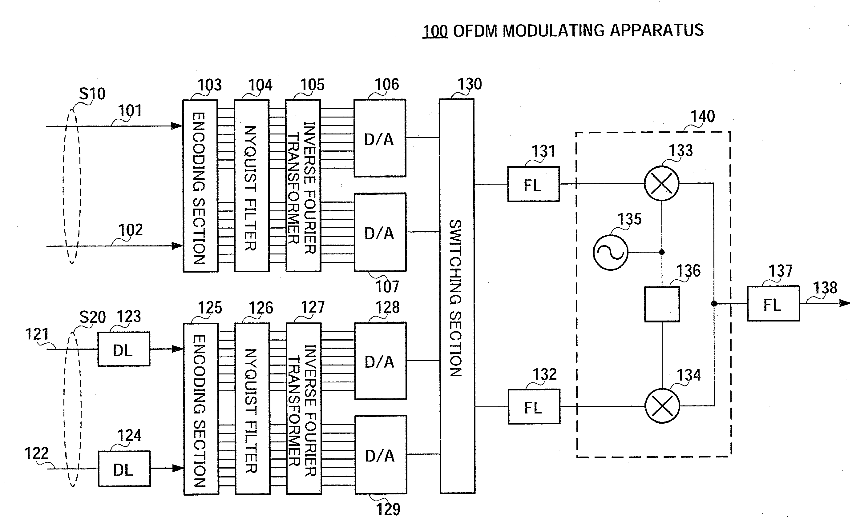
[0045]FIG. 7 shows the configuration of the OFDM modulating apparatus of the present embodiment. OFDM modulating apparatus 100 of the present embodiment can transmit twice as much information as the conventional OFDM modulating apparatus shown in FIG. 3, in substantially the same frequency bandwidth.

[0046]OFDM modulating apparatus 100 has two systems each transmitting the same amount of information as the conventional OFDM apparatus shown in FIG. 3. These will be referred to as the “first system” and the “second system,” input signal S10 is inputted in the first system and input signal S20 is inputted in the second system. These input signals S10 and S20 have the same transmission rate. Input signal S10 for the first system is formed with I axis signal 101 and Q axis signal 102, and input signal S20 for the second system is formed with I axis signal 121 and Q axis signal 122.

[0047]Input signal S10 for the first system is inputted directly to encoding section 103. By contrast with th...

embodiment 2

[0070]In Embodiment 1, two OFDM signals are multiplexed by switching and alternately selecting the first system and the second system. However, this results in cutting off power of information in the respective systems, and leads to deterioration of the error rate to some degree.

[0071]Therefore, in the present embodiment, when OFDM signals for the first system and OFDM signals for the second system are synthesized, one of OFDM signals is not cut off at all. Instead, a method is proposed of keeping the original OFDM signals as much as possible by partially keeping OFDM signals before and after switching time and permitting partial overlaps of OFDM signals.

[0072]FIG. 14, in which the same reference numerals are allotted to the corresponding sections in FIG. 7, shows a configuration of an OFDM modulating apparatus of the present embodiment. Compared to OFDM modulating apparatus 100 as shown in FIG. 7, OFDM modulating apparatus 300 has the same configuration as OFDM modulating apparatus...


PUM


Abstract

It is possible to form an OFDM signal improving frequency use efficiency. An OFDM modulation apparatus includes Nyquist filters (104, 126) for Nyquist-shaping signals (S10, S20) of two systems, delay apparatuses (123, 124) for delaying a signal of one system at ½ of the symbol period T, inverse Fourier transformers (105, 127) for OFDM-processing the respective signals after the Nyquist formation, and a switching section (130) combining the signals of the two systems by selectively outputting the signals of the two systems subjected to the OFDM processing while switching the signals at a ½ interval of the symbol period. Thus, it is possible to multiplex the two OFDM signals without interfering each other. As a result, it is possible to realize an OFDM modulation device (100) reaching twice as much as frequency use efficiency as compared to the conventional OFDM signal (i.e., reaching twice as much as the information transmission with the same frequency band as the conventional one.)

Description

TECHNICAL FIELD[0001]The present invention relates to an OFDM modulation technique for improving frequency use efficiency.BACKGROUND ART[0002]Recently, for spread of an information processing technique and rapid development of IT (Information Technology) society, demand for and expansion of information and communication is very remarkable. It is demanded that a communication infrastructure that connects an individual with a society in addition to among societies, is capable of high-speed and wireless communication. This increasing demand for mobile communication dries up rich frequency resources.[0003]Now, so-called space-division multiplexing communication is studied as a technique, such as MIMO (Multi Input Multi Output), for improving frequency efficiency by transmitting modulated signals through a plurality of antennas. That is, by using a plurality of channels formed between transmission antennas and reception antennas, the individuality between modulated signals is secured as ...

Claims


Application Information

Patent Timeline
Patent Type & Authority Applications(United States)
IPC IPC(8): H04J11/00
CPCH04L5/0007H04L27/2626H04L27/2602H04L27/26265
Inventor OHTA, GENICHIRO
Owner PANASONIC CORP
Features
  • R&D
  • Intellectual Property
  • Life Sciences
  • Materials
  • Tech Scout
  • Unparalleled Data Quality
  • Higher Quality Content
  • 60% Fewer Hallucinations
Learn More