QKD system with common-mode dithering

a technology of qkd and common mode, applied in the field of quantum cryptography, can solve problems such as intrusion errors that reveal her presen

Active Publication Date: 2009-01-22
MAGIQ TECH INC
View PDF15 Cites 12 Cited by
  • Summary
  • Abstract
  • Description
  • Claims
  • Application Information

AI Technical Summary

Benefits of technology

[0009]Another aspect of the invention is a QKD station (Bob) operably couplable to another QKD station (Alice) via an optical fiber link and a synchronization channel that supports synchronization (sync) signals having a timing TSS. The QKD station includes a modulator adapted to receive and selectively randomly modulate quantum signals sent by Alice to Bob over the optical fiber link and a detector unit optically coupled to the modulator. The QKD station also includes a controller operably coupled to the detector unit and the modulator. A variable delay is arranged between the controller and either the detector unit or the modulator. The variable delay is set to define a fixed timing interval ΔTF1 between a timing TSB for a modulator activation signal SB and a timing TS42 for a detector gating signal S42 that corresponds to an optimum detector count NMAX from the detector unit. A change in the sync signal timing TSS does not cause a change in the fixed timing interval ΔTF1, which allows for Bob's modulator and detector unit to be dithered in a “common mode” simply by dithering the sync signal timing.

Problems solved by technology

Thus, an eavesdropper (“Eve”) that attempts to intercept or otherwise measure the exchanged qubits will introduce errors that reveal her presence.

Method used


Image

  • QKD system with common-mode dithering
  • QKD system with common-mode dithering
  • QKD system with common-mode dithering

Examples


Embodiment Construction

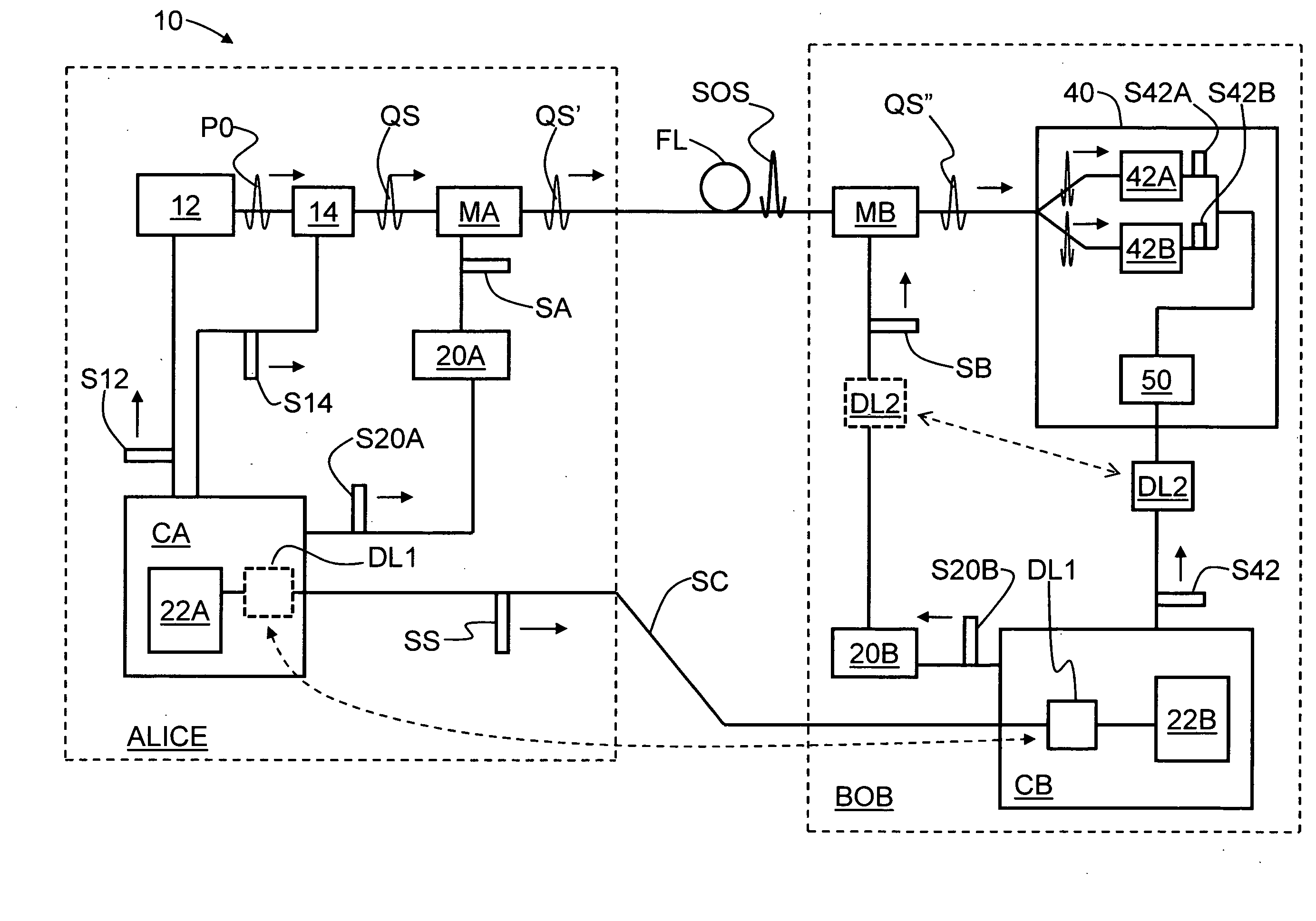
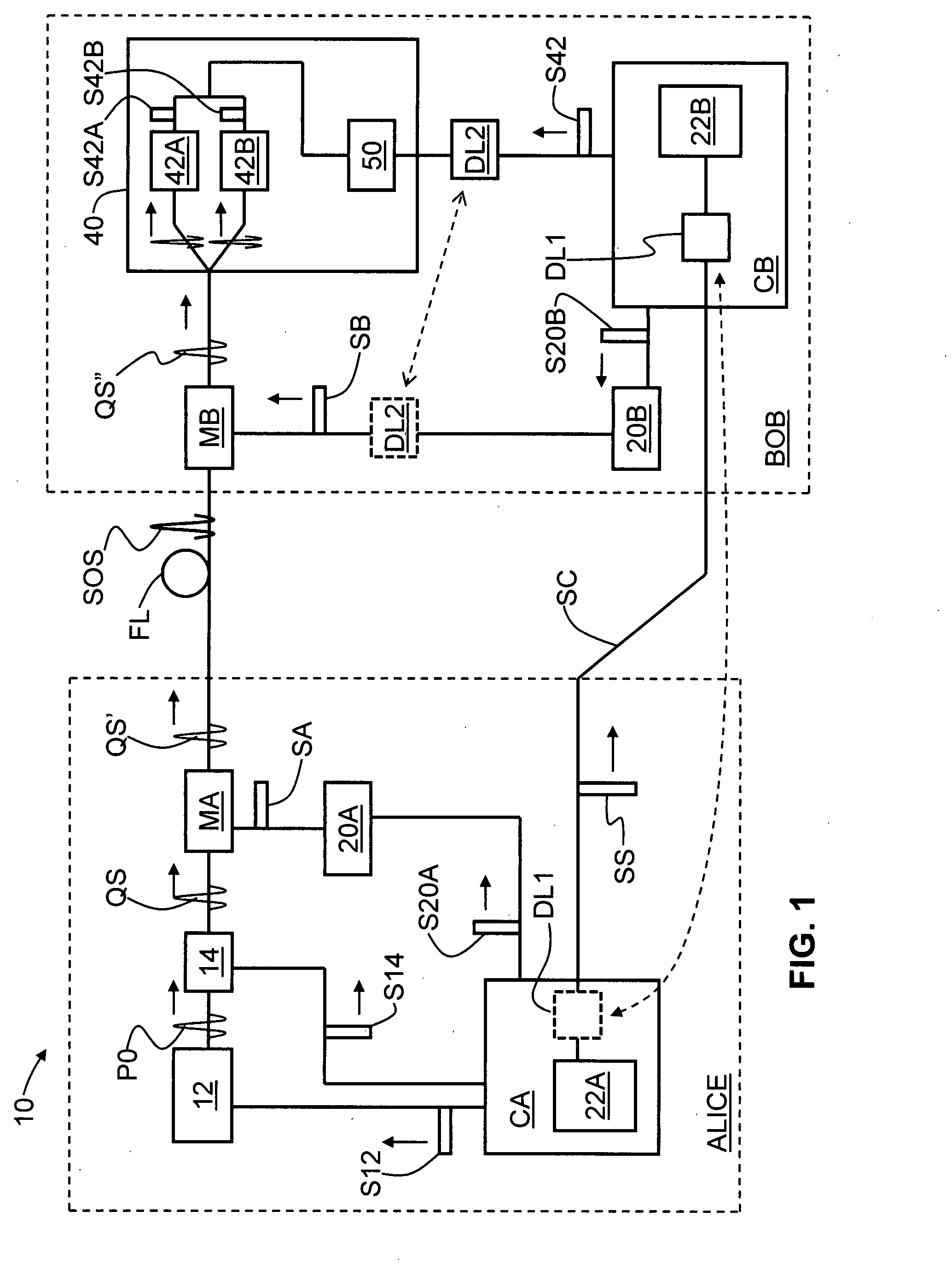
[0014]FIG. 1 is a schematic diagram of an example QKD system 10 according to the present invention, illustrating the key elements of the QKD system that allow the system to operate using the common-mode dithering method of the present invention. QKD system 10 includes a first QKD station Alice optically coupled to a second QKD station Bob via an optical fiber link FL.

Alice

[0015]Alice includes a light source 12, a variable optical attenuator 14 arranged downstream of and optically coupled to the light source, and a phase modulator MA arranged downstream of and optically coupled to the VOA. Phase modulator MA is optically coupled to optical fiber link FL and is operably coupled to a modulator driver 20A.

[0016]Alice further includes a controller CA operably coupled to light source 12, VOA 14 and modulator driver 20A. Controller CA controls the operation of light source 12 and modulator driver 20A via respective timed control signals S12 and S20A. VOA 14 is controlled so as to have a se...


PUM


Abstract

A QKD system (10) having two QKD stations (Alice and Bob) optically coupled by an optical fiber link (FL), wherein Bob includes a variable timing delay arranged between Bob's controller (CB) and modulator (MB) or detector unit (40). A set-up and calibration procedure is performed wherein delay DL2 is adjusted until the timings for the modulator and detector unit (TSB and TS42, respectively) are established. Delay DL2 is then fixed so that the detector unit and modulator operate in a common timing mode that is not changed if the synchronization signal is changed. The timing TSS of the synchronization (sync) signals (SS) sent from Alice to Bob is adjusted to arrive at optimum system performance. Once the QKD system is in operation, because the sync signal can drift, the sync signal timing TSS is dithered maintain optimum QKD system performance. Since the modulator and detector unit timing is tied together, dithering the sync signal also dithers the modulator and detector unit together in a “common mode,” rather than varying the timing of each of these elements separately.

Description

FIELD OF THE INVENTION[0001]The present invention relates to quantum cryptography, and in particular relates to quantum key distribution (QKD) systems, and systems for and methods of maintaining the performance of same during operation.BACKGROUND OF THE INVENTION[0002]Quantum key distribution (QKD) involves establishing a key between a sender (“Alice”) and a receiver (“Bob”) by using weak (i.e., 1 photon or less, on average, and typically 0.1 photon on average) optical signals or “qubits” transmitted over a “quantum channel.” Rather than relying on computational impracticality, the security of the key distribution is based on the quantum mechanical principle that any measurement of a quantum system in an unknown state will modify its state. Thus, an eavesdropper (“Eve”) that attempts to intercept or otherwise measure the exchanged qubits will introduce errors that reveal her presence.[0003]The general principles of quantum cryptography were first set forth by Bennett and Brassard in...

Claims


Application Information

Patent Timeline
Patent Type & Authority Applications(United States)
IPC IPC(8): H04L9/08H04L9/28
CPCH04L9/0852H04B10/70
Inventor VIG, HARRY
Owner MAGIQ TECH INC
Why Eureka
Try Eureka