Asynchronous non-constant-pitch spiral scroll-type fluid displacement machine

Inactive Publication Date: 2009-01-22
DAI ZHIHUANG +1
View PDF13 Cites 21 Cited by
  • Summary
  • Abstract
  • Description
  • Claims
  • Application Information

AI Technical Summary

Benefits of technology

[0011]With the aid of sophisticated computer-based real-time measurement systems and advanced computer fluid dynamics analysis, it was found that fluid pressure distribution and variation during the operation of scroll-type fluid displacement machines is key to the design of a new fluid displacement machine structure, and to choose an appropriate curve for scroll wr

Problems solved by technology

With such orbiting motion, the line contacts between the spiral vanes of the fixed and orbiting scrolls move along the curved surfaces of spiral wraps, thereby creating fluid pockets and possibly changing the volume of (and thus the pressure in) the fluid pockets.
Although this design concept of scroll-type fluid displacement machines appeared as early as the beginning of twentieth century, its development was hindered due the difficulty to optimize its design

Method used


Image

  • Asynchronous non-constant-pitch spiral scroll-type fluid displacement machine
  • Asynchronous non-constant-pitch spiral scroll-type fluid displacement machine
  • Asynchronous non-constant-pitch spiral scroll-type fluid displacement machine

Examples


Embodiment Construction

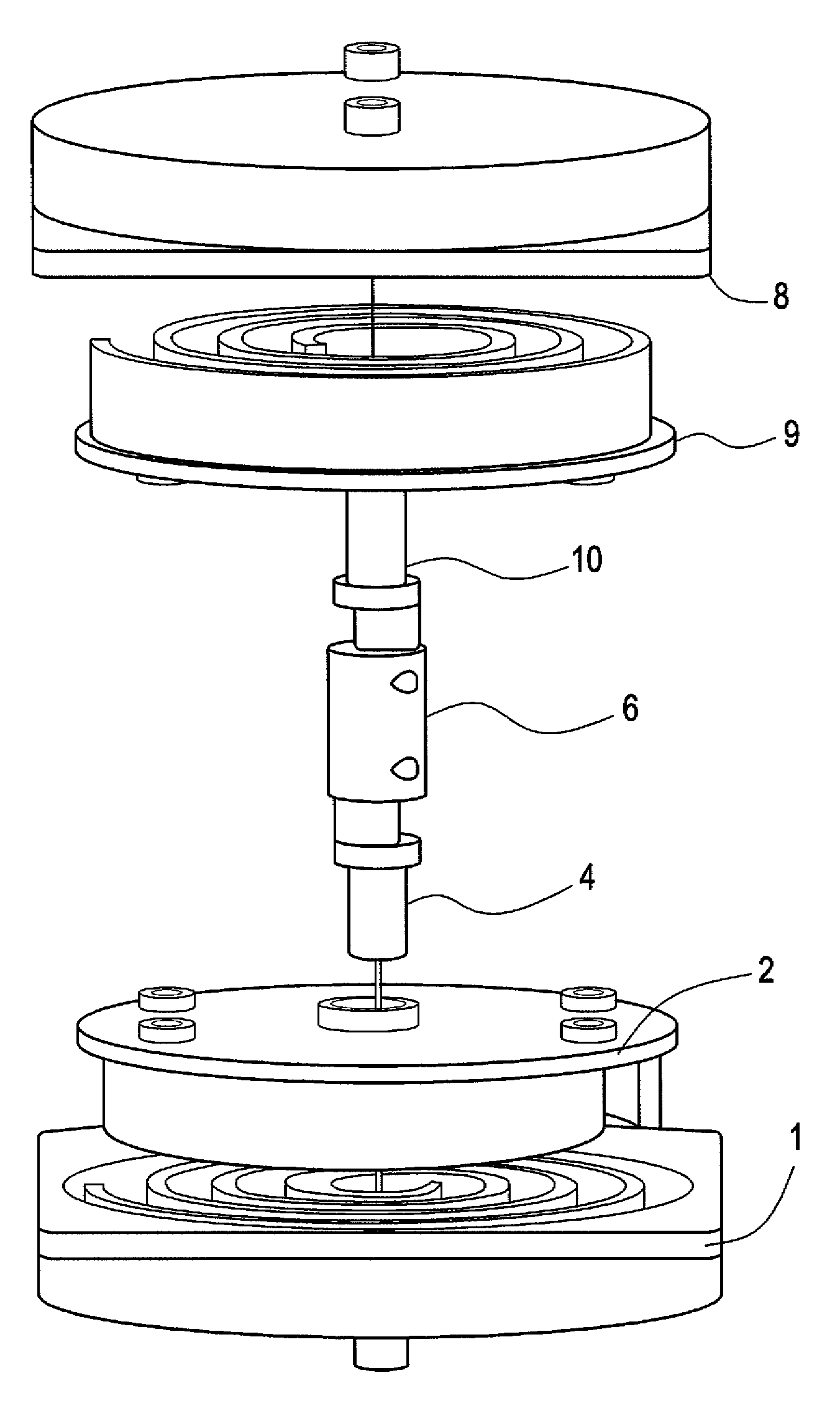
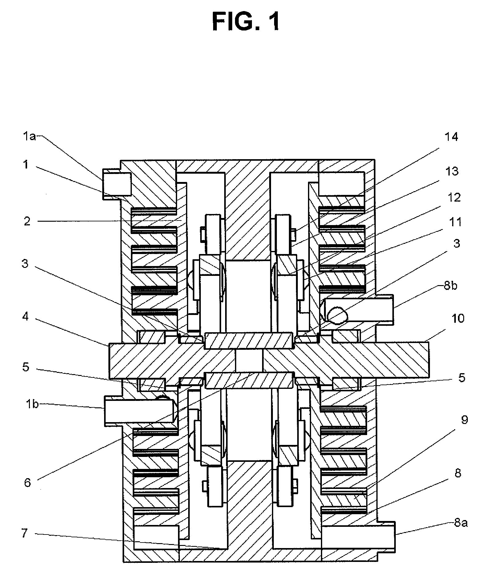
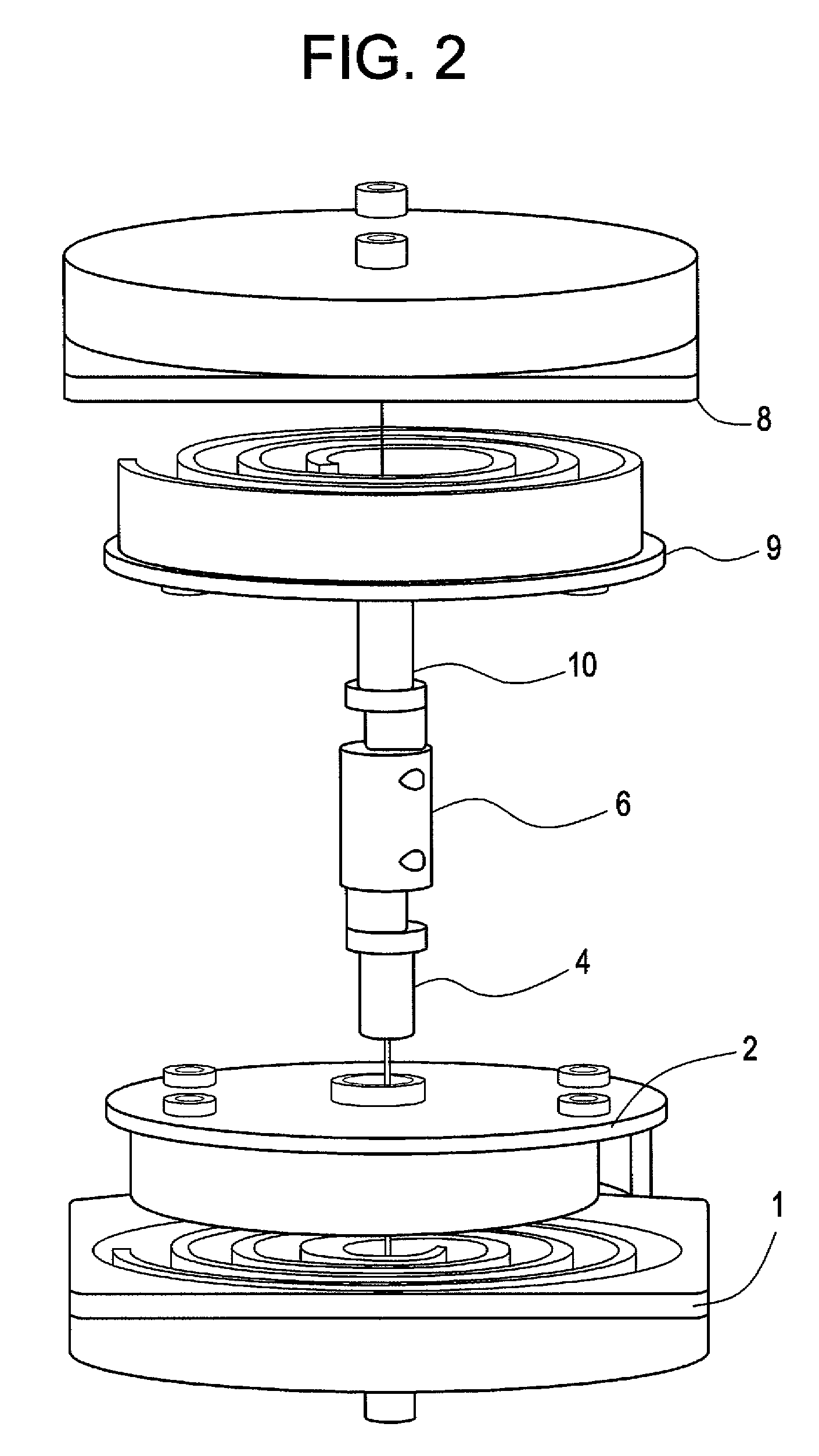
[0025]Referring to FIG. 1, the first fixed scroll 1 has its spiral wrap that interfits the spiral wrap of the first orbiting scroll 2. The concentric part of crankshaft 4 passes through the center hole of fixed scroll 1 and is supported by bearing 5 while the eccentric part of crankshaft 4 goes through the center hole of orbiting scroll 2 and is supported by bearing 3. The second fixed scroll 8 has its spiral wrap that interfits the spiral wrap of the first orbiting scroll 9. The concentric part of crankshaft 10 passes through the center hole of fixed scroll 8 and is supported by bearing 5 while the eccentric part of crankshaft 10 goes through the center hole of orbiting scroll 9 and is supported by bearing 3. The rigid coupling 6 connects crankshaft 4 and crankshaft 10. The fixed scroll 1 and fixed scroll 8 are affixed to the housing 7. The rotating force is transmitted to the end of crankshaft 10 so that the crankshaft 10 drives the orbiting scroll 9 to produce relative orbiting m...


PUM


Abstract

A scroll-type spiral fluid displacement machine having at least one pair of interfitting scroll elements. The scroll vanes of the scroll elements are constructed upon a base line spiral defined by the equation:
L=K0φK1e−φ/<sub2>K2 </sub2>
where L is the distance from the spiral's origin to any point on the spiral curve, φ is the angular displacement of the spiral, K0 is a constant greater than 1, K1, is a constant greater than 1, and K2 is a constant greater than 10.

Description

BACKGROUND OF THE INVENTION[0001]1. Field of the Invention[0002]This application relates generally to a spiral scroll-type fluid displacement machine and more particularly to an asynchronous non-constant pitch spiral scroll-type fluid displacement machine.[0003]2. Description of the Related Art[0004]Generally, a conventional spiral scroll-type fluid displacement machine is formed with a pair of scroll elements (i.e., an orbiting scroll element and a fixed scroll element) each having spiral vanes that are fitted together in a certain predetermined way to intake fluid such as air or water through an intake port. The interfitting spiral vanes create one or more fluid pockets and trap the fluid inside the pocket(s) by moving the orbiting scroll element in a predetermined manner. The fluid pocket moves toward an outlet port while maintaining pressure in the pocket by continuously moving the orbiting scroll element within the interfitted fixed scroll element. The pressurized fluid is disc...

Claims


Application Information

Patent Timeline
IPC IPC(8): F04C18/063
CPCF04C18/0269
Inventor DAI, ZHIHUANGZHAN, ZHENGZHI
Owner DAI ZHIHUANG
Why Eureka
Try Eureka