Electric connector

a technology of electric connectors and connectors, which is applied in the direction of coupling device connections, coupling parts engagement/disengagement, two-part coupling devices, etc., can solve the problems of inability to cover the contact portions of contacts with plastics materials, disadvantages in transmission characteristics of conventional connectors, and inability to remove plastics materials surrounding the press fitted and fixed portions. , to achieve the effect of adjusting the capacitance of the particular contact, easy matching and further improving the transmission characteristics

Inactive Publication Date: 2009-01-22
HOSIDEN CORP
View PDF6 Cites 24 Cited by
  • Summary
  • Abstract
  • Description
  • Claims
  • Application Information

AI Technical Summary

Benefits of technology

[0022]The electric connector is thus adapted to adjust the capacitance of the particular contact just by changing the height of the shield plate in part. Consequently, the electric connector is still further advantage

Problems solved by technology

In a connector of the above-mentioned conventional example, however, contact portions at leading ends of contacts that are press fitted and fixed in a housing are disposed outside of a dielectric housing and fully exposed to the air; in this respect, the conventional example does not have a microstrip structure in a strict sense, and sufficient impedance matches are not obtained therein.
Hence capacitance at the contact portions of the contacts is smaller than that at th

Method used


Image

  • Electric connector
  • Electric connector
  • Electric connector

Examples


Embodiment Construction

[0032]An electric connector according to an embodiment of the present invention will be described below with reference to the drawings.

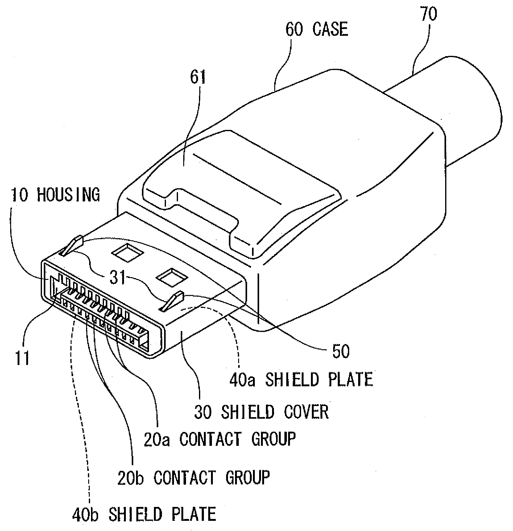
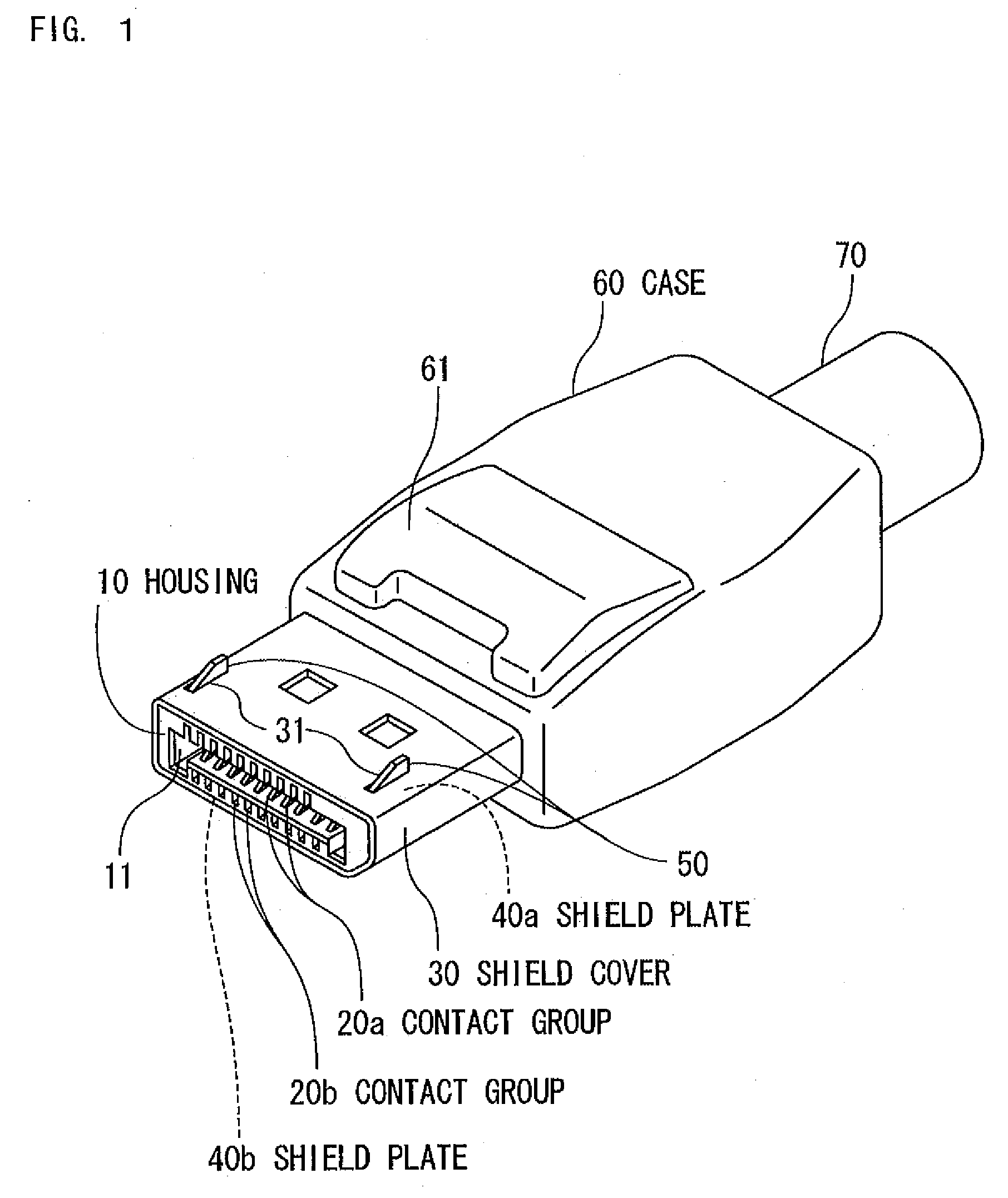
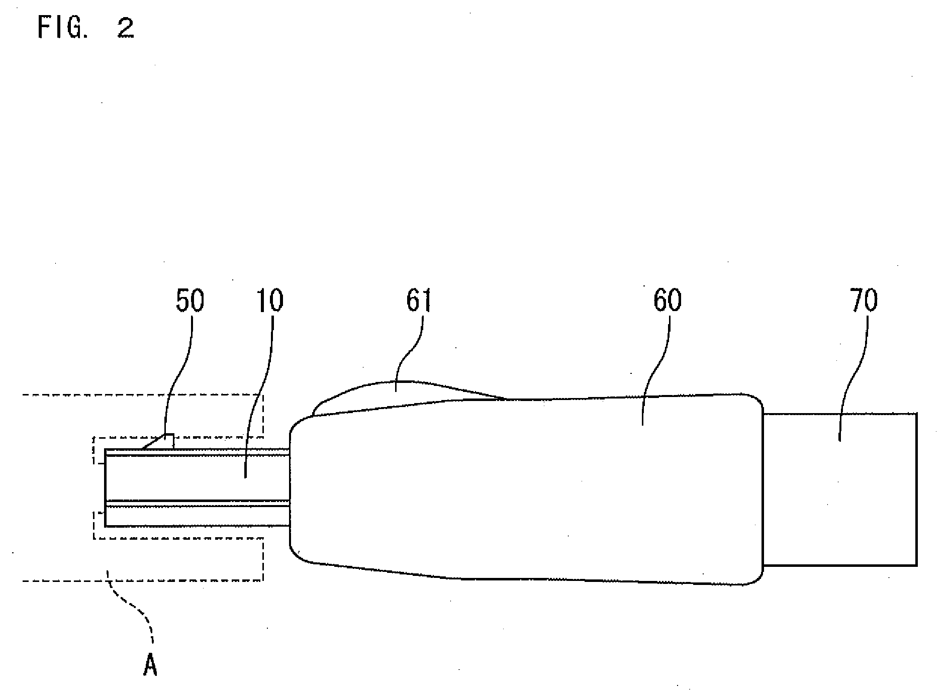
[0033]As shown in FIGS. 1 to 7, the electric connector described herein is a plug connector to be attached to a leading end of a bulk cable (a cable 70) for high-speed signal transmission. The electric connector includes a housing 10, contact groups 20a and 20b, a shield cover 30, shield plates 40a and 40b, and a case 60.

[0034]The housing 10 is an insulative member made of plastics material in a substantially rectangular solid shape, with its front side adapted to be engaged with a mating connector A (see FIG. 2) which is provided in an electronic device and the like. As shown in FIGS. 1 and 3, the housing 10 accommodates the contact groups 20a and 20b, which are laterally arranged in two rows shifted in phase from each other so as to correspond to contacts (not shown) of the mating connector A. As shown in FIGS. 4 and 5, an opening 11 to receive a p...


PUM


Abstract

An electric connector includes an insulative housing of such a shape as to be engageable on a front side thereof with a mating connector, a contact group including a plurality of contacts, a shield cover for surrounding outer surfaces of the housing, and a metal shield plate for impedance matching. The contacts are arranged in a widthwise direction of the connector so as to correspond to contacts of the mating connector. Proximal ends of the contacts are held and fixed in terminal insertion holes formed in the housing and leading ends of the contacts being exposed from the terminal insertion holes. The metal shield plate has a width thereof corresponding to a lateral length of the contact group and is disposed between the shield cover and the contact group and facing the contact group.

Description

[0001]The present application claims priority under 35 U.S.C. §119 of Japanese Patent Application No. 2007-190146 filed on Jul. 20, 2007, the disclosure of which is expressly incorporated by reference herein in its entity.BACKGROUND OF THE INVENTION[0002]1. Field of the Invention[0003]The present invention relates to electric connectors used in cables for signal transmission.[0004]2. Description of the Related Art[0005]Electric connecters for use in latest personal computers and the like are required to provide matched impedances and low crosstalk. In this regard, connectors having microstrip line structures have been proposed (see, e.g., Japanese Unexamined Patent Publication No. 05-135826).[0006]In a connector of the above-mentioned conventional example, however, contact portions at leading ends of contacts that are press fitted and fixed in a housing are disposed outside of a dielectric housing and fully exposed to the air; in this respect, the conventional example does not have ...

Claims


Application Information

Patent Timeline
IPC IPC(8): H01R13/648H01R13/6477
CPCH01R13/6474H01R13/6582H01R13/6473H01R13/6585H01R12/53H01R13/62H01R13/648H01R24/28
Inventor KONDO, HAYATONAGATA, TAKAYUKI
Owner HOSIDEN CORP
Why Eureka
Try Eureka