Position indicator and capacitor

a technology of position indicator and capacitor, which is applied in the direction of printed circuit non-printed electric components association, final product manufacture, instruments, etc., can solve the problems of large mounting space, large shape of electronic parts, and large cost of parts

Active Publication Date: 2017-04-11
WACOM CO LTD
View PDF29 Cites 0 Cited by
  • Summary
  • Abstract
  • Description
  • Claims
  • Application Information

AI Technical Summary

Benefits of technology

[0020]According to one aspect, the present invention provides a position indicator of the electromagnetic induction system and a capacitor having an adjustable capacitance value that can avoid problems as described above.
[0025]The capacitance adjusting capacitor can be formed as a minute chip capacitor, and can thus be of a small size. Therefore the position indicator can be made smaller and thinner. In addition, the capacitance adjusting capacitor is suitable for mass production and can be reduced in price, and thus contributes to reduction in price of the position indicator. The capacitance of the capacitance adjusting capacitor can be varied by trimming processing applied to the capacitance adjusting capacitor with a laser beam or the like. Thus, adjustment work can be made easier than in the case where trimmer capacitors are adjusted, and an adjustment process can be automated, so that the mass production of the position indicator is made possible.
[0026]According to the present invention, the use of the capacitance adjusting capacitor having the trimming electrode formed in a state of being exposed to the outside as a capacitor for adjusting the resonance frequency of the resonance circuit of the position indicator enables miniaturization, price reduction, facilitation of the adjustment work, and automation of the adjustment process, and can therefore solve the problems of the above-described position indicator in related art.

Problems solved by technology

However, the trimmer capacitors for the fine adjustment of the resonance frequency of the resonance circuit of the position indicator are electronic parts having a relatively large shape, and are costly parts.
However, as described above, in the case of the position indicator in related art, the trimmer capacitors, which are electronic parts having a large shape, are used for the adjustment of the resonance frequency, and thus require a large mounting space, which has been a hindrance in forming the position indicator into a thin pen shape.

Method used


Image

  • Position indicator and capacitor
  • Position indicator and capacitor
  • Position indicator and capacitor

Examples


Embodiment Construction

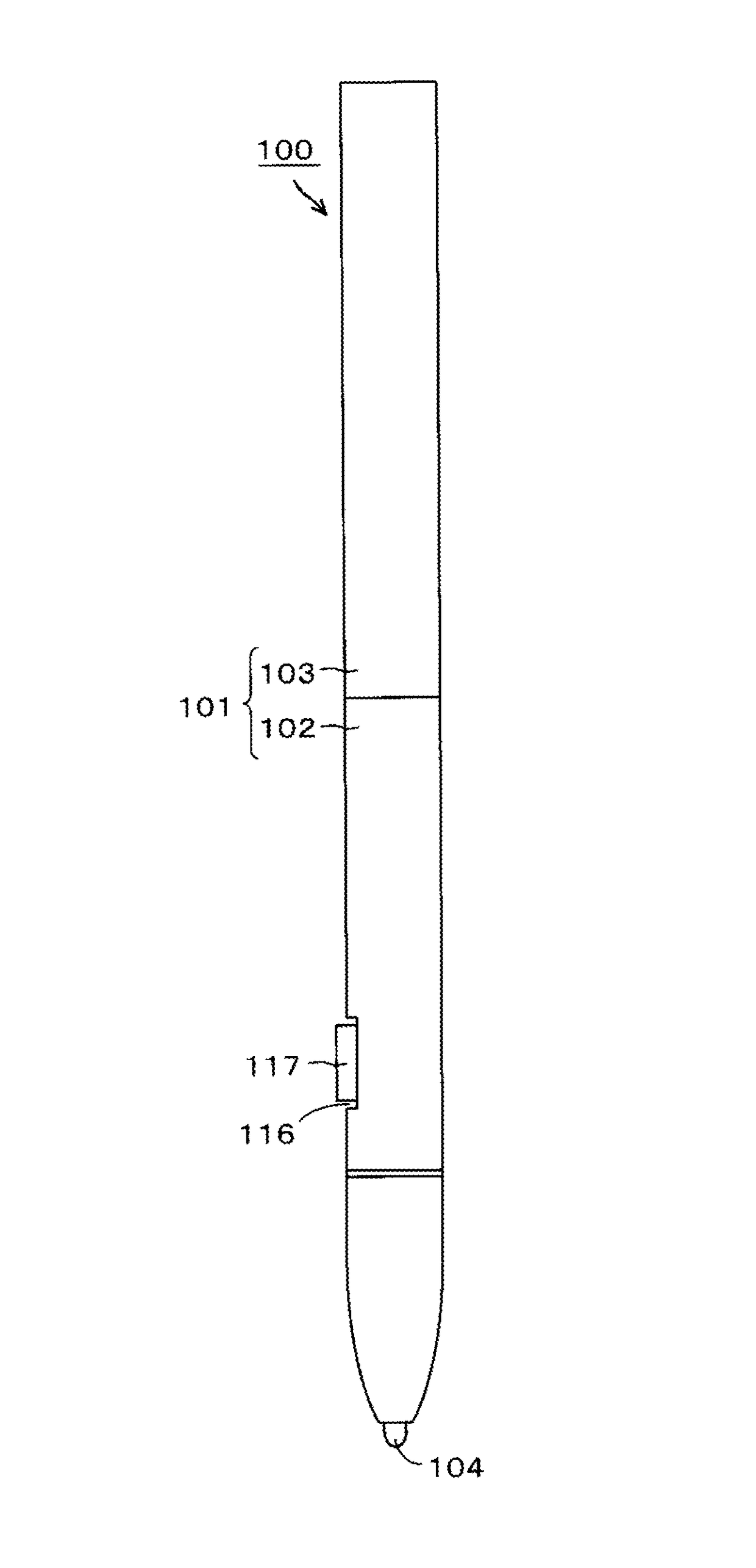
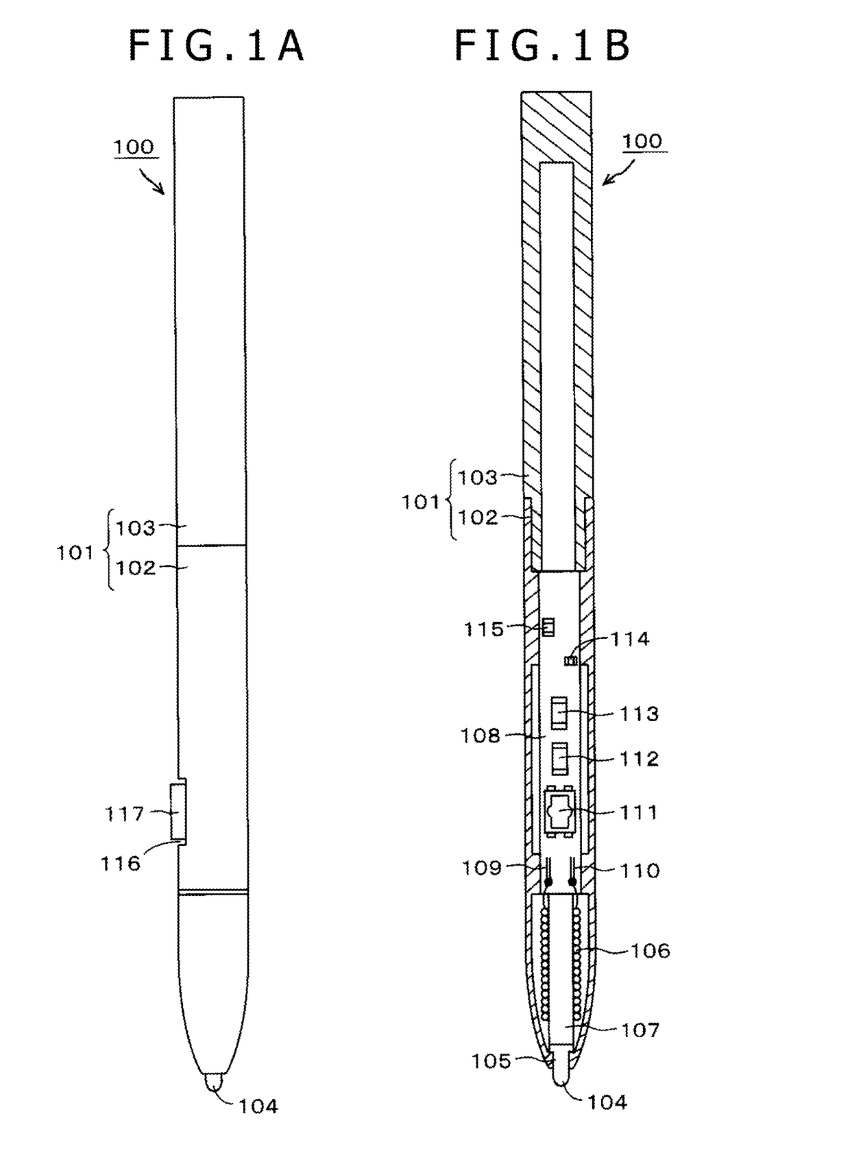
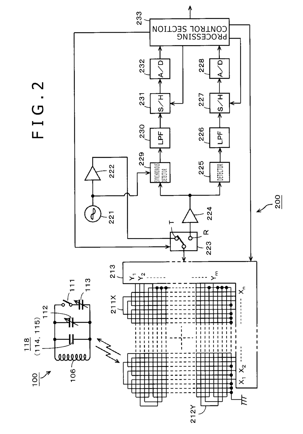
[0044]A position indicator according to the present invention has the following features.

[0045](1) The position indicator having a resonance circuit housed in a casing, the resonance circuit including an inductance element and a capacitor variable in capacitance and the resonance circuit resonating at a predetermined frequency, the position indicator being electromagnetically coupled to a position detecting device, wherein the capacitor forming the resonance circuit includes a dielectric, an electrode disposed on one side of the dielectric, and a trimming electrode disposed on another side of the dielectric such that at least one part of a region of the trimming electrode is opposed to the electrode with the dielectric interposed in between, to form the capacitance of the capacitor, the capacitor is housed in the casing such that the at least one part of the region of the trimming electrode is exposable from the casing, and the area of the at least one part of the region forming the...


PUM


Abstract

A position indicator includes a resonance circuit housed in a casing and having an inductance element and a capacitor variable in capacitance, such that the resonance circuit resonates at a predetermined frequency. The position indicator is electromagnetically coupled to a position detecting device. The capacitor includes a dielectric, an electrode disposed on one side of the dielectric, and a trimming electrode disposed on another side of the dielectric such that at least one part of a region of the trimming electrode is opposed to the electrode with the dielectric interposed in between, to form the capacitance of the capacitor. The capacitor is housed in the casing such that the at least one part can be exposed from the casing. The area of the at least one part exposed from the casing to the outside is changed so as to correspond to a resonance frequency desired for the resonance circuit.

Description

BACKGROUND[0001]Technical Field[0002]The present invention relates to a position indicator of an electromagnetic induction system and to a capacitor suitable for use as a capacitor forming a resonance circuit of the position indicator of the electromagnetic induction system.[0003]Description of the Related Art[0004]As disclosed in Patent Document 1 (Japanese Patent Laid-Open No. 2002-244806), for example, a coordinate input device of an electromagnetic induction system includes: a position detecting device having a sensor formed by disposing a large number of loop coils in an X-axis direction and a Y-axis direction of coordinate axes; and a pen-shaped position indicator having a resonance circuit including a coil wound around a magnetic core and a capacitor.[0005]The position detecting device supplies a transmission signal of a predetermined frequency to a loop coil of the sensor. The loop coil transmits the transmission signal as electromagnetic energy to the position indicator. Th...

Claims


Application Information

Patent Timeline
Patent Type & Authority Patents(United States)
IPC IPC(8): G01R27/28G01B7/004H01G4/005G06F3/038G06F3/0354H05K1/18
CPCG01B7/004G06F3/038G06F3/03545H01G4/005H05K1/181H05K2201/10015H05K2203/107H05K2203/171Y02P70/611Y02P70/50G06F3/033
Inventor HARA, KAZUOYAMAGUCHI, TAKASHI
Owner WACOM CO LTD
Why Eureka
Try Eureka