Compression Garments And A Method Of Manufacture

a compression garment and manufacturing method technology, applied in the field of compression garments, can solve the problems of reducing the effect of lymphatic drainage, affecting the quality of garments, creating undesirable effects, etc., and achieve the effect of reducing ill-fit, reducing ill-fit, and increasing stretch and recovery

Inactive Publication Date: 2009-01-29
SKINS INTEMATIONAL TRADING AG
View PDF102 Cites 129 Cited by
  • Summary
  • Abstract
  • Description
  • Claims
  • Application Information

AI Technical Summary

Benefits of technology

[0106]In garments constructed on panels cut on the horizontal plane with respect to the grain of the fabric, the present invention preferably uses articulation points of fabric inserts of similar grade stretch or recovery. Alternatively, higher levels of stretch and recovery can be used strategically to reduce this ill-fit. Ill-fitting panels means compression values are lost when required in those areas. To overcome this, the present invention can use panels cut in an ‘angle warping’ form where stretch and recovery is reversed by cutting it across the fabric grain at the different angle and degree. Normally, in the existing art, circular knit fabric has been used in the whole garment as a way of reducing this ill-fit, however circular knit is not capable of all the function requirements of the present invention.
[0107]These articulation points that relate to the knee and hip are preferably not positioned at the knee or hip itself but on panels in the near vicinity, allowing better stretch and recovery around the articulation.
[0108]Where articulations occur and the fit has to remain tight and functioning with appropriate levels of compression, the method of construction of the present invention allows shaping of the areas of the hip and knee to be taken into account by using the reduction algorithm to reduce the panel at that point by a desired amount to achieve fit. By incorporating panels cut on a different bias (a bias created not to allow the fabric used to hang to fit the form better, but a bias articulation to allow better function of body activity under load) compression can be anchored specifically to these articulation points, allowing a homogenous fit between body and garment.

Problems solved by technology

This alters the effect of the static compression and can create undesirable effects, in being undesirably tight or in providing more compression in the wrong places.
In turn, this can impede circulation and reduce the effect of lymphatic drainage.

Method used


Image

  • Compression Garments And A Method Of Manufacture
  • Compression Garments And A Method Of Manufacture
  • Compression Garments And A Method Of Manufacture

Examples


Embodiment Construction

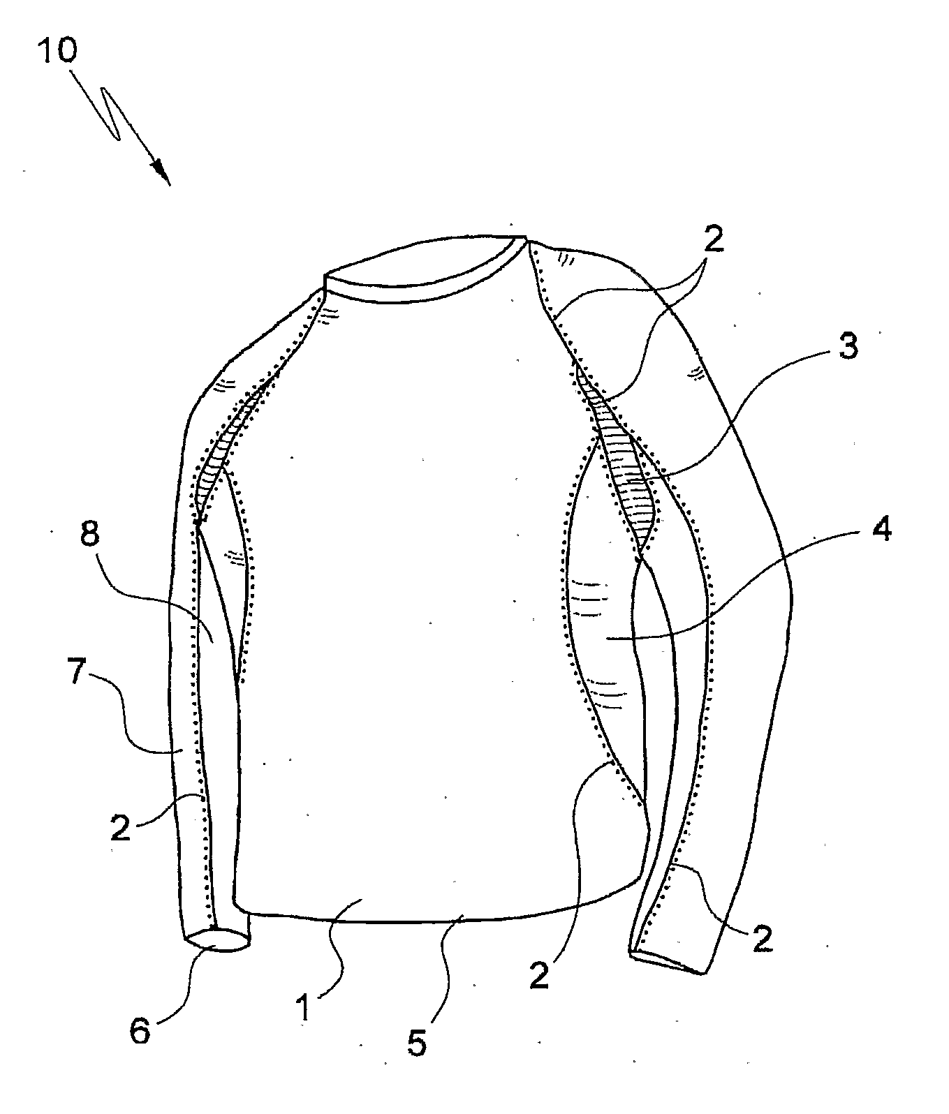
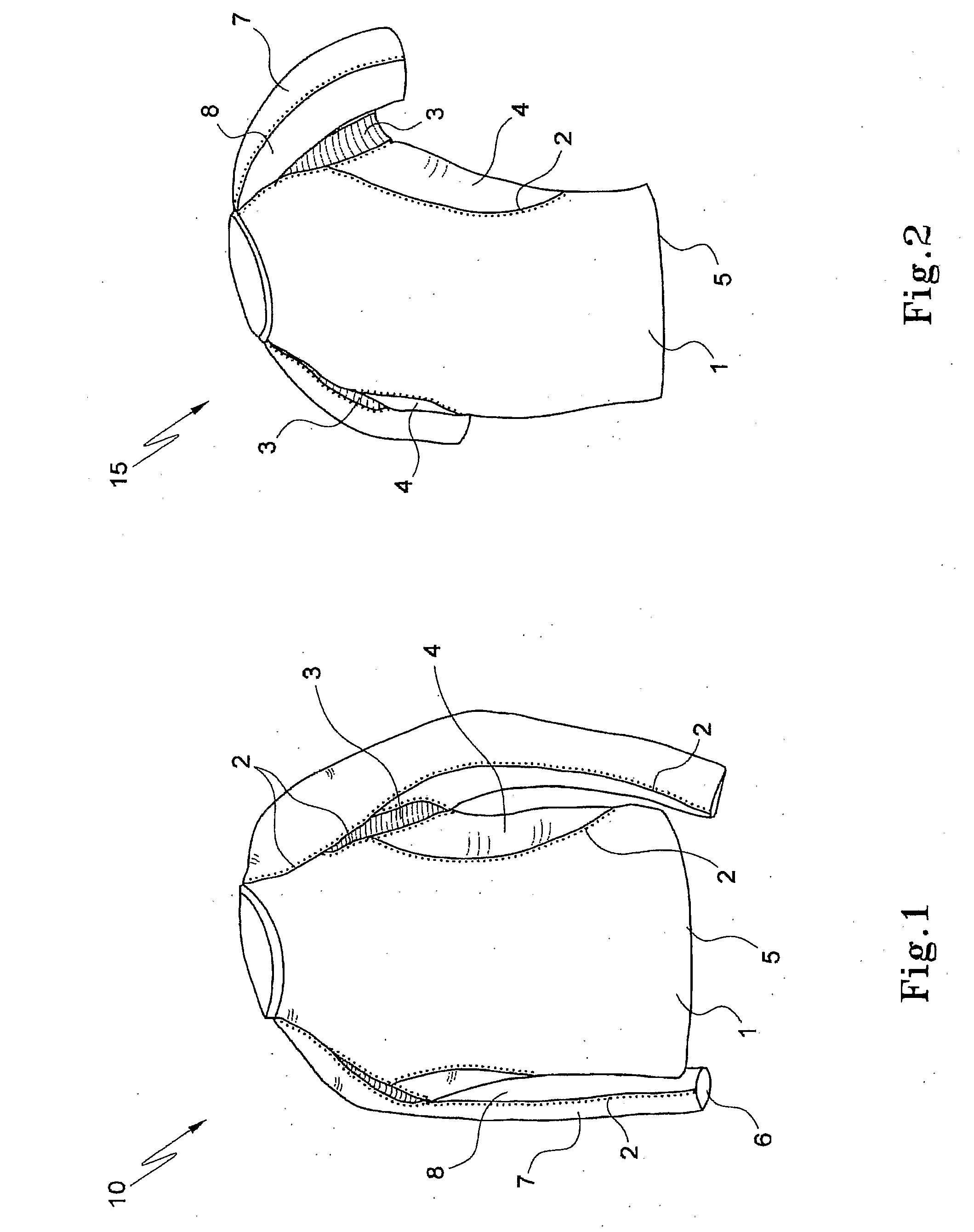
[0137]Referring to the drawings in detail, FIG. 1 shows a garment 10 having a body 1 with four- or six-needle flat bed stitching 2 situated in anatomical positions along the garment, namely along the serratus anterior muscle group. An area 3 under the armpits uses fabric of either a different or a higher compression level (including compositions of higher stretch Elastane) than that of body 1. Similar fabric to that used in area 3 is used on side panels 4 running along the sides of garment 10 to create better compression. Bottom edge 5 of garment 10 is hemmed in a manner that allows stretch and does not create a lateral pressure ridge. The wrist hem 6 is of similar design and constructions, so that pressure is not placed against the wearer's wrist (not shown).

[0138]The sleeves of garment 10 have an outer panel 7 and an inner panel 8. These can be of similar construction and specification to those of garment body 1, or they may be different to a muscle proprioception. The stitching 2...


PUM


Abstract

The invention provides a compression garment (50) for clothing a body part, such as a lower torso and the legs. The body part includes a muscle ridge, such as a lateral edge of the gluteus maximus (49). Compression garment (50) has first and second panels of stretchable material joined by a seam (32). At least part of the seam (32) is adapted to correspond to at least part of the muscle ridge, being at the edge of the gluteus maximus (49). The invention also provides a method of manufacturing a compression garment, using an algorithm to calculate size changes to produce desired compression.

Description

TECHNICAL FIELD[0001]The present invention relates to compression garments and to methods of manufacture. In particular, this invention is concerned with compression garments such as shorts, long tights and tops, either as single garments or in a combination of garments worn as a suit.BACKGROUND[0002]A detailed discussion of the prior art and studies relating to muscles and muscle activity is contained in Australian Provisional Patent Application No 2004995456 (the “Provisional Application”), the contents of which are imported herein by reference.[0003]Prior art compression garments are designed to fit the body snugly, but without consideration as to the extent to which muscles increase in bulk and mass during activity. Such prior art garments can become non-static or counter-gradient in this situation. Once a person wearing a static compression garment increases muscle mass with activity, the garment can become tighter in the vicinity of the muscle, which can increase as much as 3-...

Claims


Application Information

Patent Timeline
Patent Type & Authority Applications(United States)
IPC IPC(8): A41D1/00A41D1/06A41D27/00
CPCA41D13/0015A41D31/185A41D1/08A41D2600/10A41H42/00A41D31/18A41D1/04
Inventor DUFFY, BRADLEY T.DUFFY, SUSAN K.
Owner SKINS INTEMATIONAL TRADING AG
Why Eureka
Try Eureka