Method for assembly of an LED light

Active Publication Date: 2009-01-29
GOODRICH LIGHTING SYST
View PDF4 Cites 2 Cited by
  • Summary
  • Abstract
  • Description
  • Claims
  • Application Information

AI Technical Summary

Benefits of technology

[0022]Further useful for an automatic quality assurance are the integration of temperature sensors monitoring the heating of the LEDs and thus detecting a correct thermal coupling, as well as an automated monitoring of the used components by optical and electric checking methods and by the checking of chromaticity coordinates as performed in a control computer for the

Problems solved by technology

These known systems, however, are not suited for the assembly process of LED lights provided for illumination of surfaces or spaces, as is the case in reading or seat lights for use in a vehicle such as, e.g. an airplane, a train or a bus.

Method used


Image

  • Method for assembly of an LED light
  • Method for assembly of an LED light

Examples


Embodiment Construction

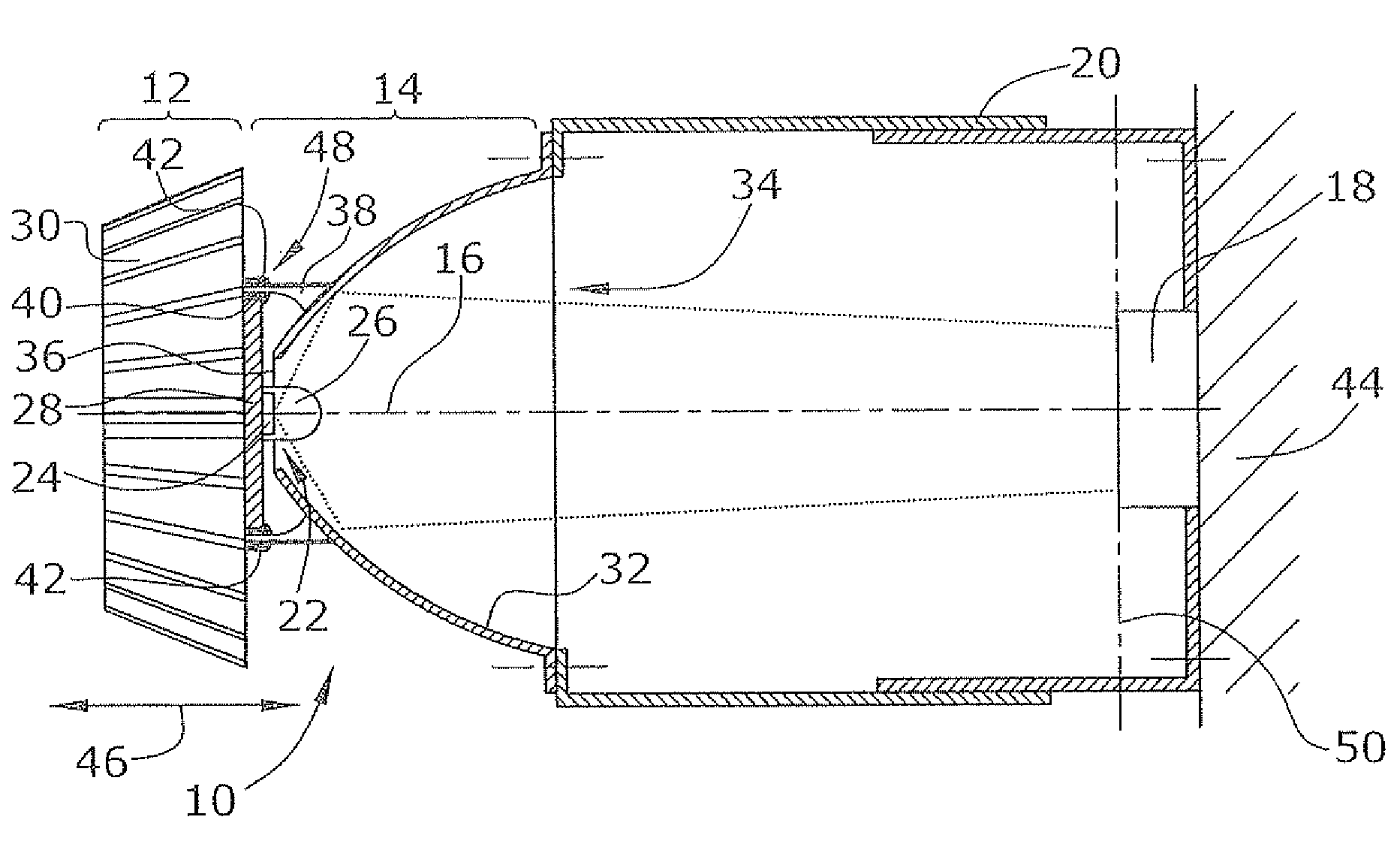
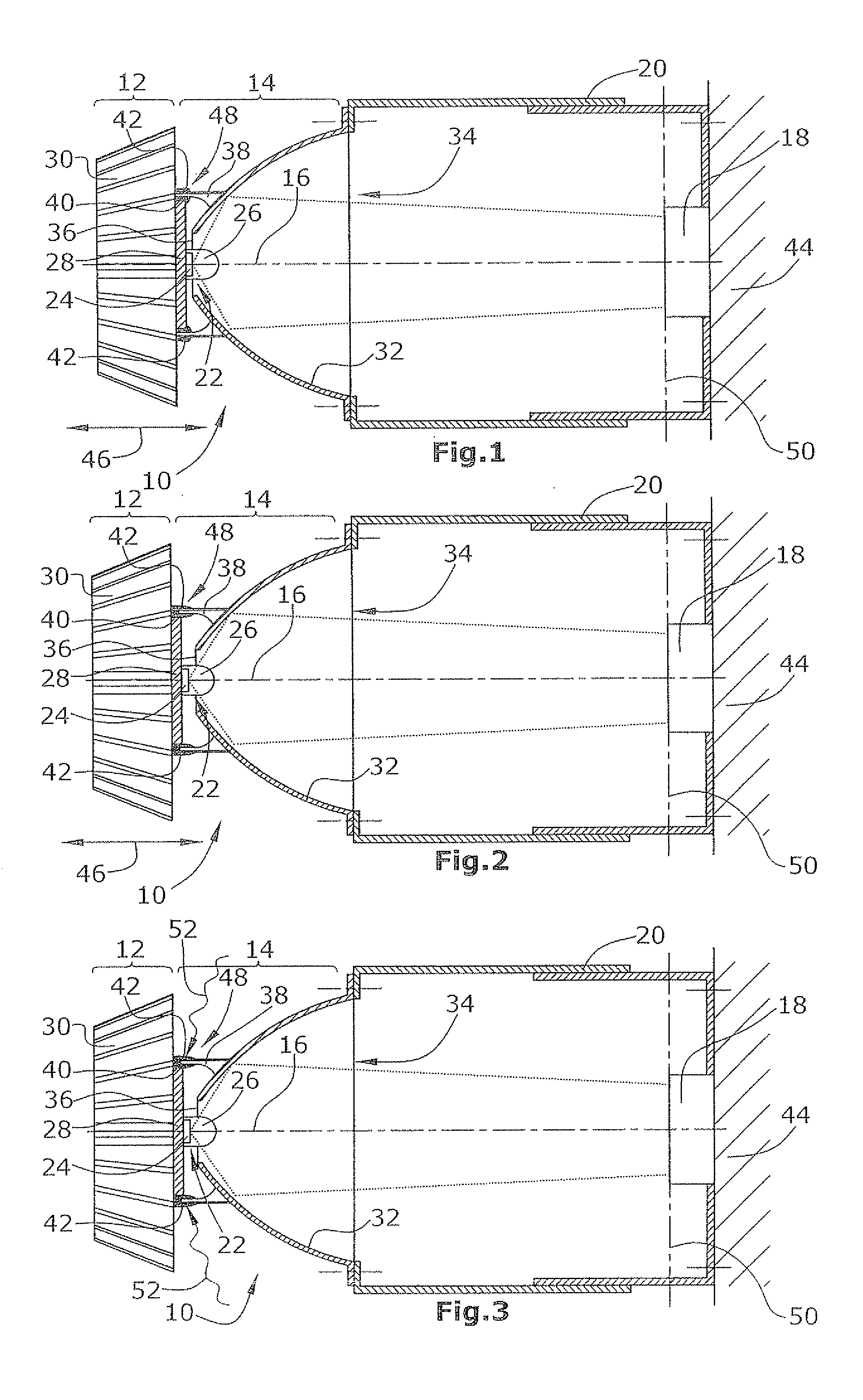
[0028]FIGS. 1 to 3 schematically illustrate an assembly and measuring arrangement for automatic fixation of two components of an LED lighting device. The LED lighting device 10 comprises a LED module 12 and an optical unit 14. These two components of LED lighting device 10 are subject to tolerances. To nonetheless be able to achieve a required light intensity at a required distance from the LED lighting device 10, it is provided that, during the assembly process, the two components are displaced relative to each other along the optical axis 16 of LED lighting device 10 until, by means of a detector 18, a relative position corresponding to the required light intensity has been found. Detector 18 is located internally of a preferably telescopable tube 20, with detector 18 arranged on one end of said tube 20 and optical unit 14 arranged on the opposite, other end of tube 20. Tube 20 is preferably telescopable in order to make it possible, with the aid of the measuring arrangement, to m...


PUM

PropertyMeasurementUnit
Massaaaaaaaaaa

Abstract

The method for assembly of an LED lighting device comprising an LED module and a reflective and / or refractive optical unit and provided particularly as a reading or seat light for use in a vehicle such as, e.g., an airplane, a train or a bus, comprises the following steps:providing an LED module (12) comprising at least one LED (22),providing a reflective and / or refractive optical unit (14) for illuminating a measuring plane by use of electromagnetic radiation from the LED module (12) and with the aid of said optical unit,arranging the optical unit (14) and the LED module (12) for later fixation to each other,driving the LED module (12) to cause it to emit electromagnetic radiation for illuminating a measuring plane,detecting at least a part of the electromagnetic radiation of the LED module (12) that is incident on the measuring plane, by use of a detector (18),moving the LED module (12) relative to the optical unit (14) and / or the optical unit (14) relative to the LED module (12) along the optical axis (16), until the detector (18) detects electromagnetic radiation of the LED module (12) of a presettable intensity, andfixing the optical unit (14) and the LED module (12) relative to each other in their current relative positions.

Description

RELATED APPLICATIONS[0001]This application claims priority of U.S. Provisional Application No. 60 / 939,516 filed May 22, 2007, European Patent Application No. 07108613.6 filed May 22, 2007, and European Patent Application No. 0801709.7 filed Feb. 18, 2008, all of which are hereby incorporated herein by reference in their entireties.BACKGROUND[0002]1. Field of the Invention[0003]The present invention relates to method for assembly of an LED lighting device which can be, for instance, a reading or seat light for use in a vehicle such as, e.g. an airplane, a train or a bus, and which comprises an LED module and an optical unit which can be of the reflective type (e.g. a reflector) and / or the refractive type (e.g. a lens).[0004]2. Related Prior Art[0005]The specification of lighting devices usually includes requirements with regard to brightness, color, and light distribution. Lighting devices comprise, apart from an illuminant, also optical systems; to be counted among these are reflect...

Claims


Application Information

Patent Timeline
IPC IPC(8): G01R31/28
CPCF21V17/101F21Y2101/02G02B27/62F21K9/00F21V29/70Y10T29/4913Y10T29/49133Y10T29/49004F21V7/0066B60Q3/44B60Q3/76F21Y2115/10
Inventor FERLING, SONJALUDER, SASCHAGRIESBACH, MARTINHESSLING, ANDRE
Owner GOODRICH LIGHTING SYST
Why Eureka
Try Eureka