In-ceiling mount type air conditioner and indoor unit thereof

a technology of air conditioner and mounting bracket, which is applied in the direction of heating types, domestic cooling devices, lighting and heating devices, etc., can solve the problems of increasing manufacturing costs, increasing the number of parts, and displaced starting point of swing range of the flap, and achieves easy attachment/detachment, easy attachment and removal, and easy attachment

Active Publication Date: 2009-01-29
PANASONIC INTELLECTUAL PROPERTY MANAGEMENT CO LTD
View PDF9 Cites 118 Cited by
  • Summary
  • Abstract
  • Description
  • Claims
  • Application Information

AI Technical Summary

Benefits of technology

[0016]Therefore, an object of the present invention is to provide an indoor unit of an in-ceiling mount type air conditioner in which a heat insulating effect can be obtained without increasing the height dimension of the indoor unit.
[0017]Furthermore, another object of the present invention is to provide an indoor unit of an in-ceiling mount type air conditioner in which the displacement of a swing range of a flap can be reduced even when the flap warps.
[0018]Still furthermore, a further object of the present invention is to provide an in-ceiling mount type air conditioner having a simple structure for temporarily tacking a face panel, so that the number of parts can be reduced and thus the manufacturing cost can be reduced.

Problems solved by technology

However, the flap is designed in an elongated shape, and also it is a resin molded article, so that it may be warped (deformed) by heat of blown-out air or the like.
Therefore, there is a risk that the start point of the swing range of the flap is displaced.
Therefore, there are problems that the structure is complicated, the number of parts is increased and the manufacturing cost is increased.
However, in the above air conditioner, the manufacturing cost is increased because the permanent magnet and the metal plate are required, and also it is also required to provide a special mechanism for securing the permanent magnet and the plate to the corner panel and the face panel, so that the part structure is complicated.

Method used


Image

  • In-ceiling mount type air conditioner and indoor unit thereof
  • In-ceiling mount type air conditioner and indoor unit thereof
  • In-ceiling mount type air conditioner and indoor unit thereof

Examples


first embodiment

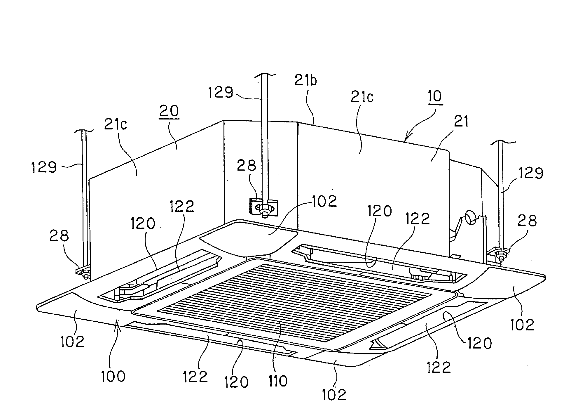
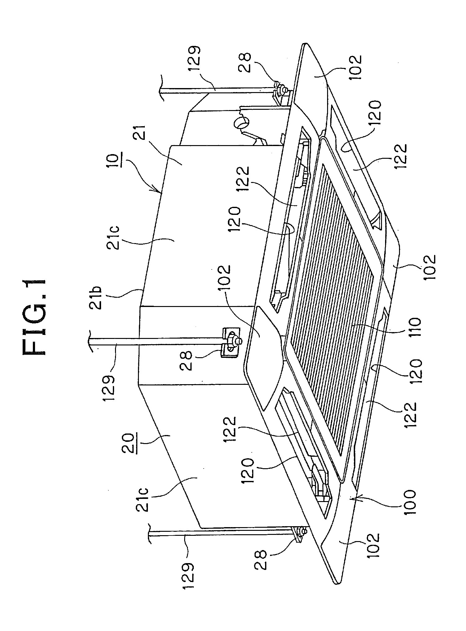
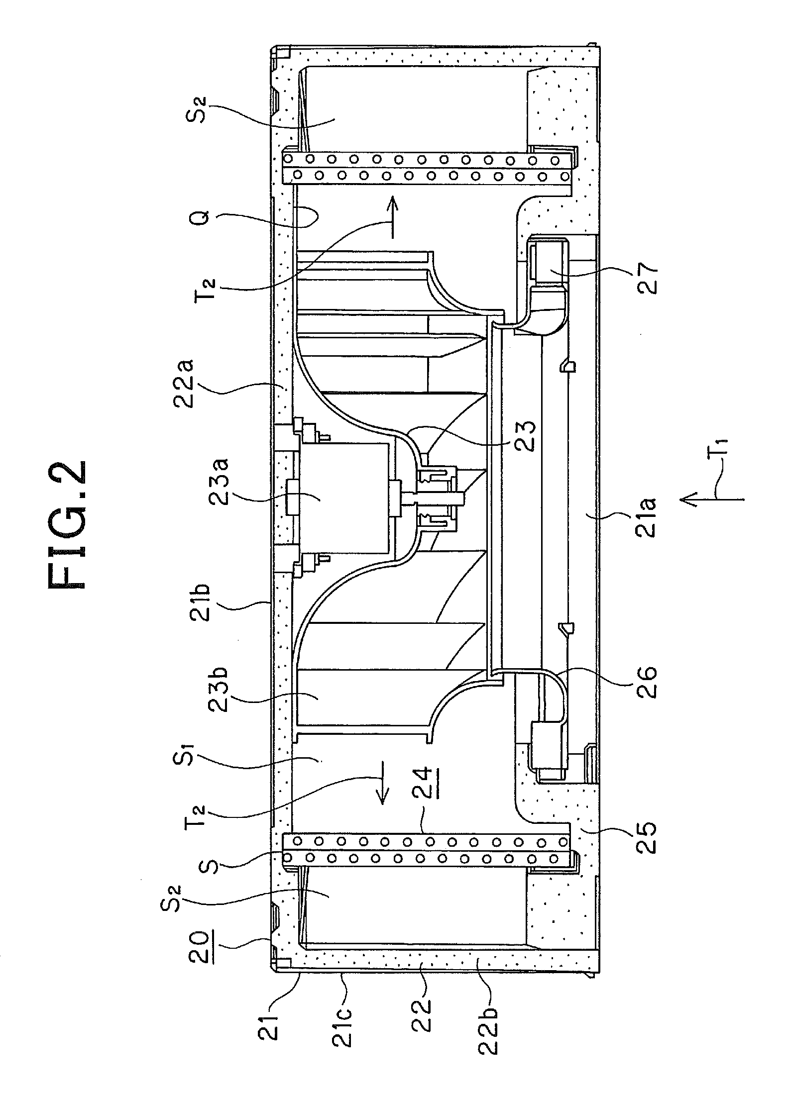
[0071]A first embodiment according to the present invention will be described hereunder with reference to the accompanying drawings. FIG. 1 is a perspective view showing an indoor unit 10 of an in-ceiling mount type air conditioner which is viewed from the lower surface side, and FIG. 2 is a longitudinally-sectional view of an indoor unit main body 20. In this embodiment, a four-way cassette type and mini cassette type indoor unit of 600mm x 600mm in outer shape will be described as an example of the indoor unit 10. However, the present invention is not limited to the above type, and it may be applicable to an two-way type indoor unit or a four-way type indoor unit having a general outer shape.

[0072]As shown in FIG. 1, the indoor unit 10 of the air conditioner has an indoor unit main body 20 which is inserted into a fixing opening portion provided to a ceiling plate from the room side, and a face panel 100 secured to the indoor unit main body 20 from the lower side.

[0073]The indoor ...

second embodiment

[0097]FIG. 9 is an enlarged perspective view showing the air blow-out port 1209 and the flap 122 formed in the face panel 100, and FIG. 10 is an enlarged view of the support portion of the flap. FIG. 11 is a planar view showing a state that the corner panel 102 is detached and a fixing seat for a stepping motor is secured to the face panel 100. FIG. 12 is a perspective view showing the fixing seat 30 for the stepping motor, and FIG. 13 is a perspective view showing the flap 122 as a single body.

[0098]The flap 122 extends substantially over the entire length in the longitudinal direction of the air blow-out port 120 as shown in FIGS. 1 and 9. Two fixing seats 30 for supporting one end in the longitudinal direction of the flap 122 is provided at one corner portion at the upper left side of FIG. 5 out of the four corner portions of the face panel 100 (that is, no fixing seat 30 is provided at the other three corner portions). One end of the flap 122 is supported by the fixing seat 30 a...

third embodiment

[0120]FIG. 14 is a perspective view showing the housing 21 assembled to the suspending fittings 28, and FIG. 15 is a diagram showing a assembling process of the suspending fittings 28 to the housing 21.

[0121]As described above, the suspending fittings 28 are respectively fixed to the four corners of the housing 21, and the suspending bolts 129 penetrate through the suspending fittings 28, whereby the housing 21 is suspended from the ceiling by the suspending bolts 129. As shown in FIG. 15, each of the suspending fittings 28 comprises a first portion 31 extending in the housing 21, a second portion 32 and a third portion 33. The second portion 32 extends substantially in parallel to the top plate portion 21b at the outside of the housing 21 when the first portion 31 is inserted through an opening (not shown) formed in the housing 21 in a direction of an arrow P and then rotated in a direction of an arrow R until the confronting surface 31a of the first portion 31 abuts against the in...


PUM


Abstract

An indoor unit of an in-ceiling mount type air conditioner including a box-shaped housing having a top plate portion, a side plate portion and an opening portion at the lower portion thereof, a face panel detachably mounted on the opening portion of the housing, an indoor heat exchanger through which the inside of the housing is compartmented into a primary side and a secondary side, and an air blower secured to the top plate portion of the housing that faces the primary side, has a primary side heat insulating material is provided to the top plate portion so as to face the primary side of the housing and a secondary side heat insulating material provided to the side plate portion so as to face the secondary side of the housing, wherein the primary side heat insulating material is provided with an opening portion through which the air blower is fixed to the top plate portion.

Description

INCORPORATION BY REFERENCE[0001]The present application claims priority under 35 U.S.C. §119 to Japanese Patent Application No. 2007-192761 filed on Jul. 25, 2007, Japanese Patent Application No. 2007-192762 filed on Jul. 25, 2007, Japanese Patent Application No. 2007-203776 filed on Aug. 6, 2007, and Japanese Patent Application No. 2007-203822 filed on Aug. 6, 2007. The content of the applications is incorporated herein by reference in its entirety.BACKGROUND OF THE INVENTION[0002]1. Field of the Invention[0003]The present invention relates to an in-ceiling mount type air conditioner.[0004]2. Description of the Related Art[0005]An indoor unit of an in-ceiling mount type air conditioner has a box-shaped housing having an opening portion at the lower side thereof. The inside of the housing is compartmented into a primary space and secondary space by an indoor heat exchanger. The primary space is partitioned by a top plate portion of the housing and the indoor heat exchanger, and indo...

Claims


Application Information

Patent Timeline
Patent Type & Authority Applications(United States)
IPC IPC(8): F25D23/00F25D17/06F24F1/0047F24F1/0063
CPCF24F1/0007F24F13/14F24F13/20F24F13/32F24F13/1426F24F1/0018F24F1/0022F24F2013/0616F24F2001/0037F24F1/0047F24F1/0063F24F2221/14
Inventor KOGA, SEIICHIOGURA, NOBUHIROHAYASHI, YOSHIKAZU
Owner PANASONIC INTELLECTUAL PROPERTY MANAGEMENT CO LTD
Why Eureka
Try Eureka