Ice-making tray

a technology for ice-making trays and trays, which is applied in the field of ice-making trays, can solve the problems of non-uniformity and non-uniformity of the caulking state, and achieve the effects of shortening the heater current-flowing time, and reducing the temperature difference of each par

Inactive Publication Date: 2009-01-29
PANASONIC CORP
View PDF10 Cites 17 Cited by
  • Summary
  • Abstract
  • Description
  • Claims
  • Application Information

AI Technical Summary

Benefits of technology

[0010]The present invention relates to an ice-making tray capable of shortening the heater current-flowing time by evening the transmission of heat from the heater, and enabling the temperature, after the termination of current flow to the heater, to easily lower by reducing the temperature difference of each part to speed up the next ice-making cycle. The ice-making tray of the present invention includes an attachment part; a tray part made of metal; a heater for heating the tray part; and at least one heater guide. The tray part is formed as a separate body from the attachment part. The heater guide is made of metal and comes into contact with the heater and the tray part. The heater guide is attached to the attachment part and holds the heater, and transmits the heat of the heater to the tray part.
[0011]In such configuration, the tray part can be manufactured by press work, and the thickness becomes substantially even. When the current flows to heater, the heat is transmitted to the tray part from a site where the heater is closely attached to the tray part by the heater guide and a site where the heater guide and the tray part are closely attached. Thus heat is transmitted from a great number of sites. Taking also into consideration that the thickness of the tray part is even, the heat is evenly transmitted to the tray part in a short period of time. The speed of the next ice-making cycle becomes faster. Thus, by enhancing the heat transmission efficiency from the heater to the tray part by the heater guide, the heater current flow can be reduced, and the ice-making cycle can be shortened.

Problems solved by technology

However, a caulking state is not necessarily always the same.
The transmission of heat to all cells 2 of ice-making tray 1 thus becomes non-uniform due to unevenness in the thickness of ice-making tray 1 and unevenness in caulking.

Method used


Image

  • Ice-making tray
  • Ice-making tray
  • Ice-making tray

Examples


Embodiment Construction

[0036]Embodiments of the present invention will be described below with reference to the drawings. It should be noted that the present invention is not limited to these embodiments.

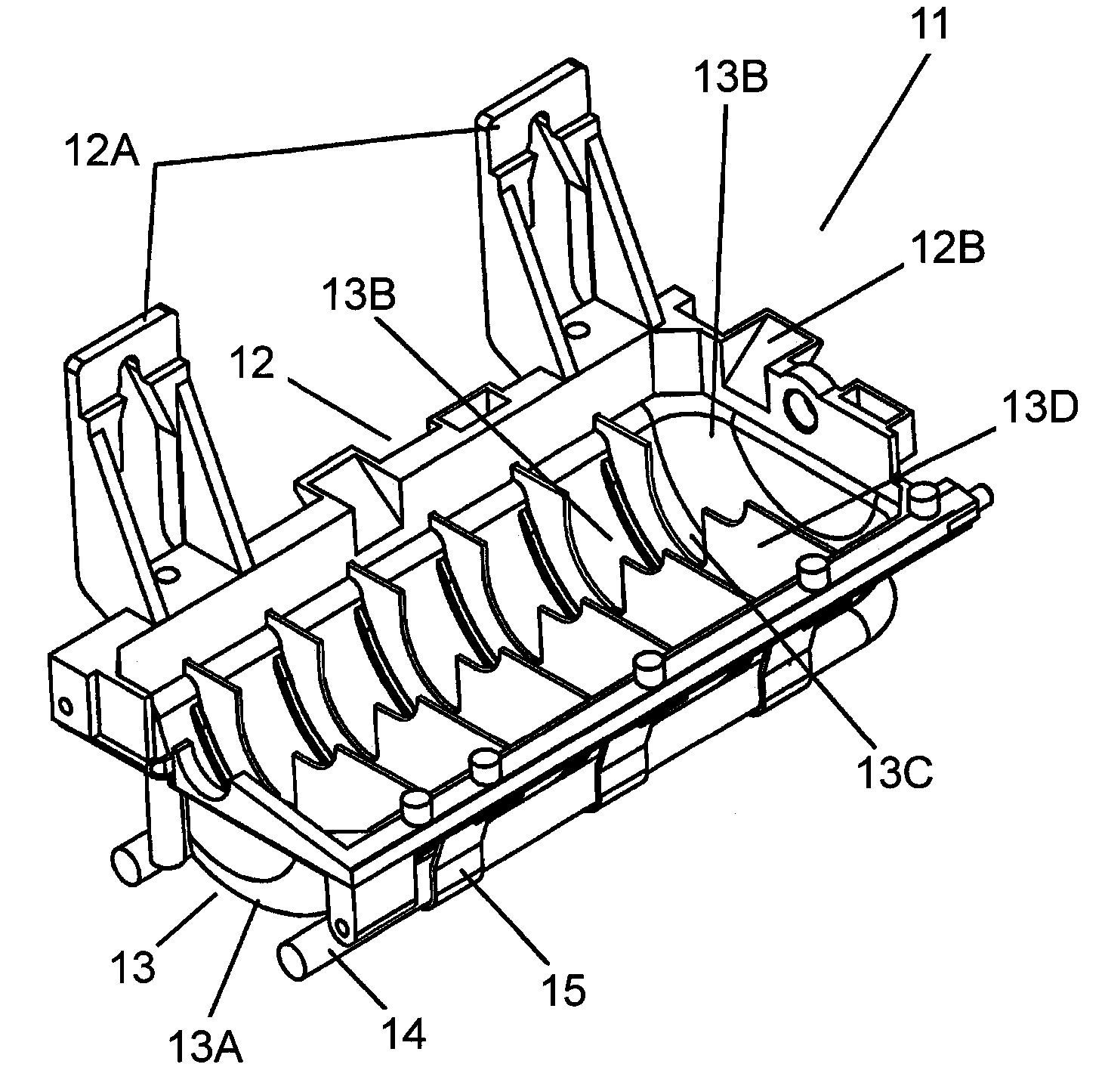
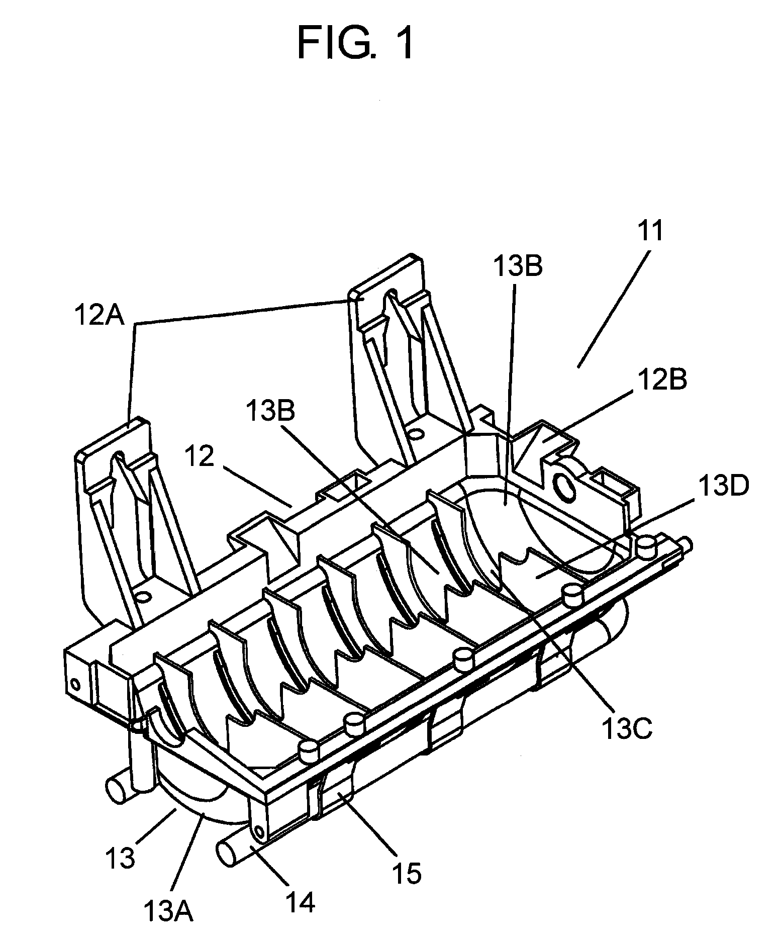
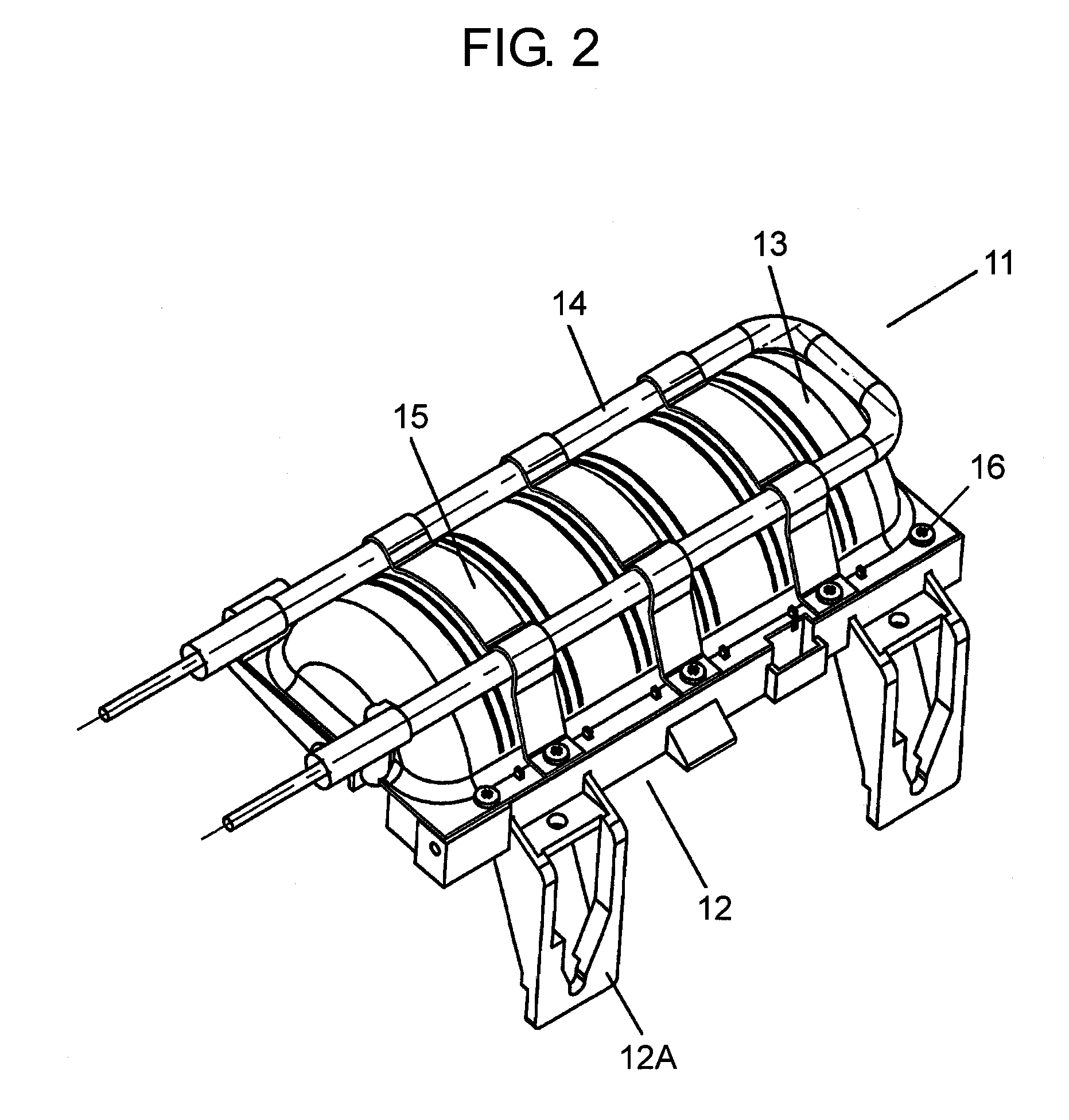
[0037]FIG. 1 is a perspective view of an ice-making tray according to an embodiment of the present invention, FIG. 2 is a perspective view of the ice-making tray seen from below, and FIG. 3 is a perspective view of an automatic ice-making device including the ice-making tray. FIG. 4 is a perspective view of a heater guide in the ice-making tray, and FIG. 5 is a cross sectional view of the ice-making tray. Ice-making tray 11 includes attachment part 12 for fixing ice-making tray 11 to a refrigerator or the like, metal tray part 13 formed as a separate body from attachment part 12, heater 14, and heater guide 15.

[0038]Tray part 13 has bottom surface 13A of semicircular cross section, and, for example, six partition plates 13D coupled to bottom surface 13A. Partition plate 13D divides the interior of tray pa...


PUM

PropertyMeasurementUnit
lengthaaaaaaaaaa
shapeaaaaaaaaaa
thermal conductivityaaaaaaaaaa

Abstract

An ice-making tray includes an attachment part; a metal tray part; a heater for heating the tray part; and at least one heater guide. The tray part is formed as a separate body from the attachment part. The heater guide is made of metal and comes into contact with the heater and the tray part. The heater guide is attached to the attachment part to hold the heater, and transmits heat of the heater to the tray part.

Description

TECHNICAL FIELD[0001]The present invention relates to an ice-making tray, arranged in a freezing compartment of a household refrigerator or the like, for making ice by supplying water and cooling the same.BACKGROUND ART[0002]An ice-making tray arranged in a freezing component of a fridge-freezer is entirely formed by aluminum die cast molding, for example. Such the ice-making tray is disclosed in Patent Document 1. A conventional ice-making tray will be described below with reference to the drawings. FIG. 8 is a perspective view of an ice-making tray used in a conventional fridge-freezer. FIG. 9 is a cross sectional view of the ice-making tray shown in FIG. 8.[0003]Ice-making tray 1 is formed by die cast molding an aluminum alloy, which is a metal having high thermal conductivity. Ice-making tray 1 includes plural cells 2 for temporarily retaining water, and attachment part 5 for fixing to the wall face of a refrigerator or the like, with screws. Cell 2 and attachment part 5 are int...

Claims


Application Information

Patent Timeline
Patent Type & Authority Applications(United States)
IPC IPC(8): F25C1/24
CPCF25C1/04F25C5/08F25C1/22
Inventor SHOUKYUU, MASATOSHITSUJIMOTO, AKINORI
Owner PANASONIC CORP
Why Eureka
Try Eureka