Frequency mode of locking phased arrays for synthesizing high order traveling interference patterns

a phased array and frequency mode technology, applied in the field of antennas, can solve the problems of complex circuitry required to generate proper phase offset, high cost of feeder circuitry, and high cost of system overall cos

Inactive Publication Date: 2009-01-29
ZUCKER OVED
View PDF6 Cites 4 Cited by
  • Summary
  • Abstract
  • Description
  • Claims
  • Application Information

AI Technical Summary

Benefits of technology

[0007]According the present invention, the elements of a phased array antenna are driven by different frequencies, rather than the same frequency, to realize a scanning beam. The scan rate of the beam may be set arbitrarily high according to the frequencies used to drive the phased array, without expensive phase modulators. In particular, each successive element of the phased array antenna is driven with a frequency that is offset from the frequency used to drive the previous element in direct proportion to the spacing between antenna elements. Thus, for a straight line implementation of a phased array antenna with an antenna spacing offset of λ / 2, the frequency offset between adjacent antenna elements is constant.

Problems solved by technology

A problem with the conventional phased array system is that the feeder circuitry is very expensive, comprising up to forty percent of the overall cost of a system.
Moreover, the circuitry required to generate proper phase offsets is complex and limits the travel velocity or scan rate of the beam.

Method used


Image

  • Frequency mode of locking phased arrays for synthesizing high order traveling interference patterns
  • Frequency mode of locking phased arrays for synthesizing high order traveling interference patterns
  • Frequency mode of locking phased arrays for synthesizing high order traveling interference patterns

Examples


Embodiment Construction

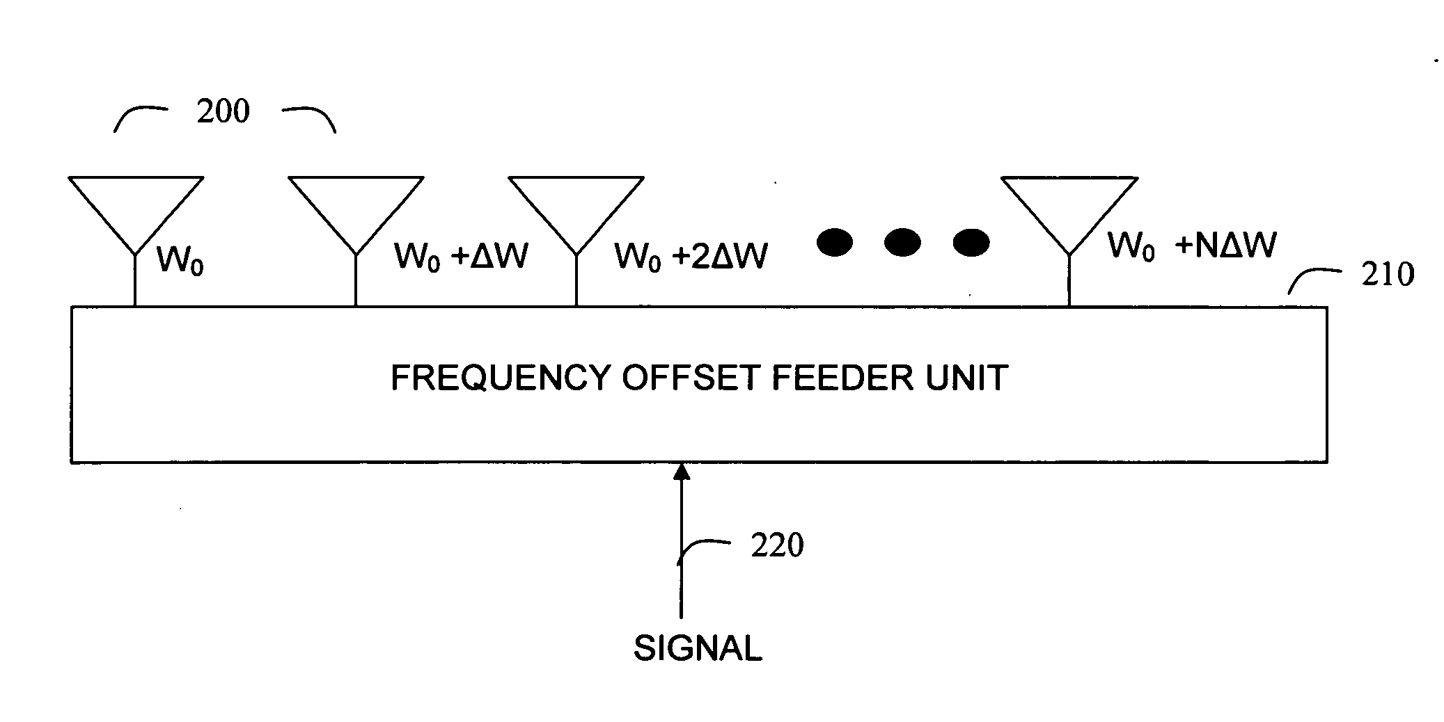
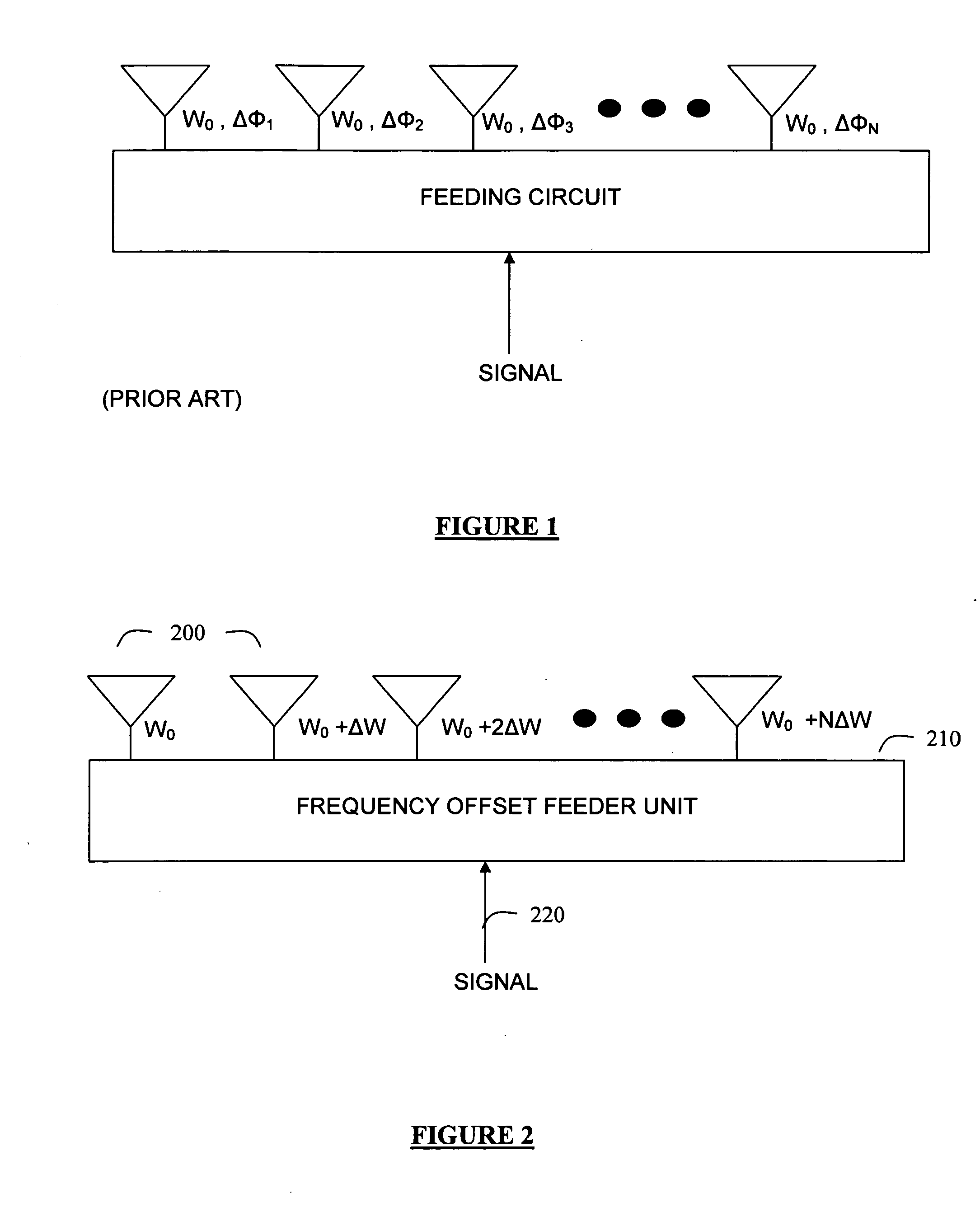
[0015]According the present invention, the elements of a phased array antenna are driven by different frequencies, rather than the same frequency, to realize a scanning beam. The scan rate of the beam may be set arbitrarily high according to the frequencies used to drive the phased array, without expensive phase modulators. In particular, each successive element of the phased array antenna is driven with a frequency that is offset from the frequency used to drive the previous element in direct proportion to the spacing between antenna elements. Thus, for a straight line implementation of a phased array antenna with an antenna spacing offset of λ / 2, the frequency offset between adjacent antenna elements is constant.

[0016]FIG. 2 depicts a phased array antenna system for transmitting signals according to an embodiment of the present invention. Referring to FIG. 2, the phased array antenna includes antenna elements 200, which are offset from each other with a constant spacing, for examp...


PUM


Abstract

The elements of a phased array antenna are driven by different frequencies, rather than the same frequency, to realize a scanning beam. The scan rate of the beam may be set arbitrarily high according to the frequencies used to drive the phased array, without expensive phase modulators. In particular, each successive element of the phased array antenna is driven with a frequency that is offset from the frequency used to drive the previous element in direct proportion to the spacing between antenna elements. Thus, for a straight line implementation of a phased array antenna with an antenna spacing offset of λ/2, the frequency offset between adjacent antenna elements is constant. For implementations of phased array antennas with another linear or a non-linear spatial relationship between antenna elements, the frequency offset between adjacent antenna elements is determined based on a linear or non-linear spatial relationship of the antenna.

Description

FIELD OF THE INVENTION[0001]The present invention relates to antennas and, more particularly, to a frequency mode of locking phased arrays for synthesizing high order traveling interference patterns.BACKGROUND OF THE INVENTION[0002]Phased array antennas have been used for many years to allow electronic scanning. In general, a phased array antenna operates by feeding a set of radiating elements (a planar array) with phase shifters in such a way that the phase variations along the array follow an arithmetic progression whose common difference is the phase shift between two adjacent elements. The phased array so configured generates a plane wave whose direction depends on this phase difference. While some phase shifters described above, still others are active and incorporate amplifiers.[0003]Phased array antennas are useful for a variety of applications. One desirable application of phased array antennas is in the implementation of steerable beams for communications, RADAR, remote mon...

Claims


Application Information

Patent Timeline
Patent Type & Authority Applications(United States)
IPC IPC(8): H01Q3/22
CPCH01Q3/22
Inventor ZUCKER, OVED
Owner ZUCKER OVED
Why Eureka
Try Eureka