Ultrasonic diagnostic apparatus

a diagnostic apparatus and ultrasonic technology, applied in ultrasonic/sonic/infrasonic diagnostics, instruments, heat measurement, etc., can solve the problem that the ultrasonic diagnostic apparatus cannot detect a maximum temperatur

Inactive Publication Date: 2009-01-29
GE MEDICAL SYST GLOBAL TECH CO LLC
View PDF11 Cites 15 Cited by
  • Summary
  • Abstract
  • Description
  • Claims
  • Application Information

AI Technical Summary

Benefits of technology

[0039]In the ultrasonic diagnostic apparatus according to the sixteenth aspect, the surface temperature of

Problems solved by technology

The above conventional ultrasonic diagnostic apparatus cannot detect a maximum temperature in the case where a maximum temperature point exists between one temperature sensor and another temperature sensor.
Therefore, there

Method used


Image

  • Ultrasonic diagnostic apparatus
  • Ultrasonic diagnostic apparatus
  • Ultrasonic diagnostic apparatus

Examples


first embodiment

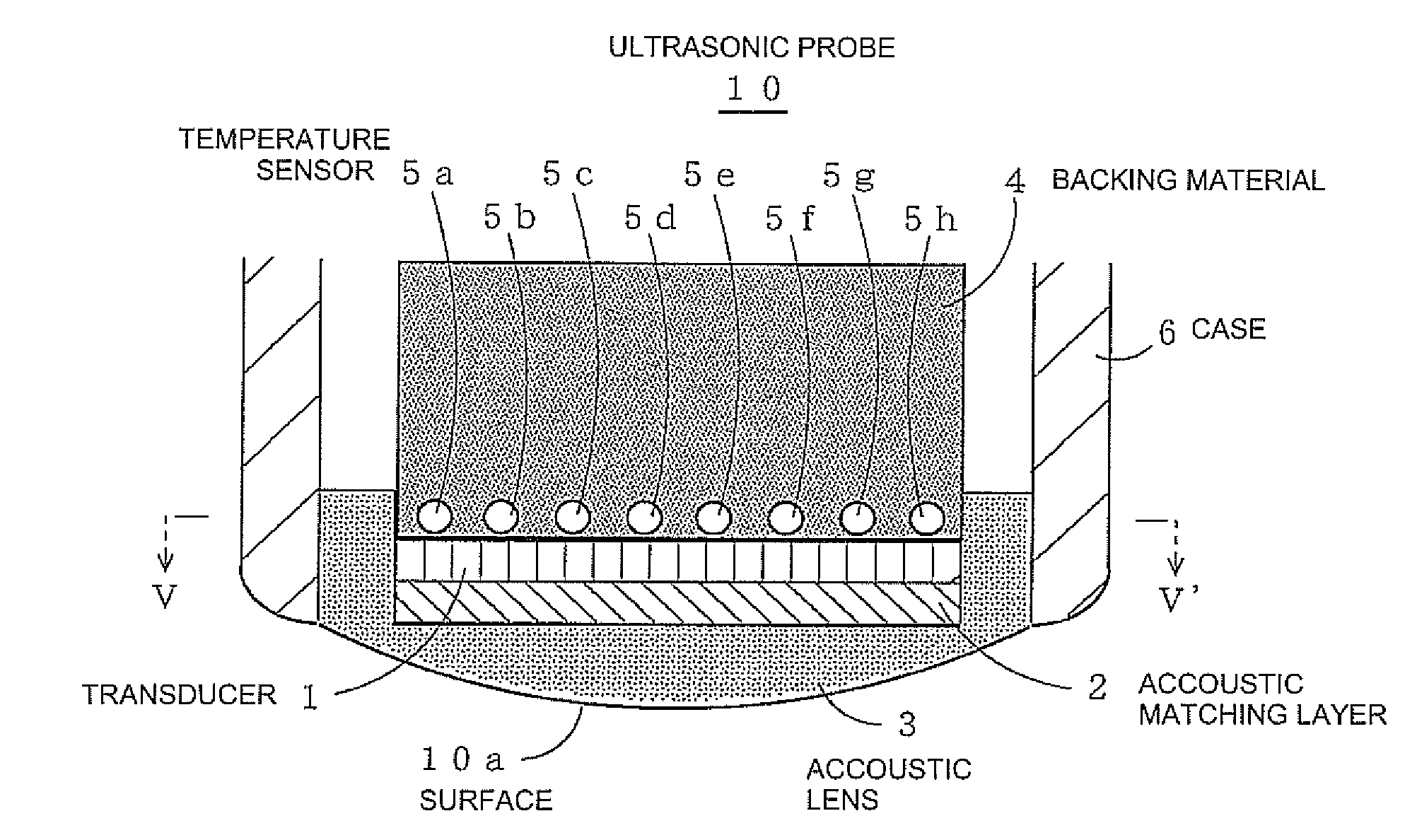
[0053]FIG. 1 is a partially cross-sectional view showing an ultrasonic diagnostic probe 10 according to a first embodiment. FIG. 2 is a cross-sectional view taken along a line V-V′.

[0054]The ultrasonic diagnostic probe 10 is a convex type ultrasonic probe which includes a large number of transducers 1, an acoustic matching layer 2, an acoustic lens 3, a backing material 4, plural temperature sensors 5a to 5h that are arranged in the vicinity of the transducers 1 (in the vicinity of the surface 10a), and a case 6.

[0055]One hundred or more transducers 1 are arranged in the lateral direction of FIG. 1, and about several transducers 1 are arranged in a direction perpendicular to the paper surface of FIG. 1. The plural temperature sensors 5a to 5h are arranged at regular intervals in the lateral direction of FIG. 1.

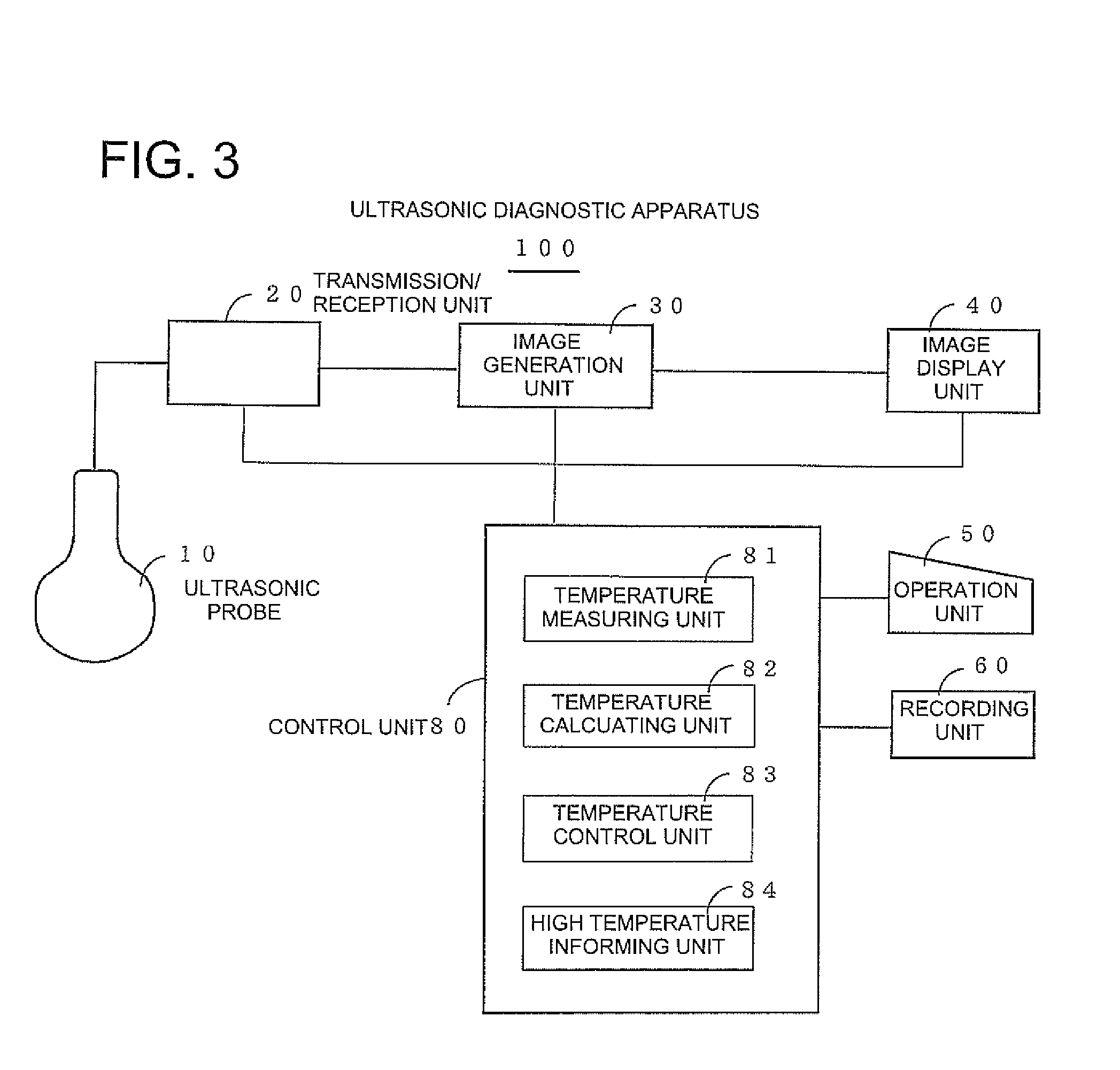
[0056]FIG. 3 is a structural block diagram showing an ultrasonic diagnostic apparatus 100 according to a first embodiment.

[0057]The ultrasonic diagnostic apparatus 100 include...

second embodiment

[0064]As shown in FIG. 6, alternatively, in the temperature calculation unit 82, the Gaussian function (or quadratic function, or the raised cosine function) is curve-fitted at seven points consisting of the maximum temperature td among the detected temperatures ta to th, the detected temperatures tc and te that are adjacent to the maximum temperature td, and the detected temperatures ta, tb, tf, and tg, which are further outside of the detected temperatures tc and te. Then, the maximum temperature Tp can be obtained from the obtained temperature profile G.

third embodiment

[0065]As shown in FIG. 7, alternatively, in the temperature calculation unit 82, the Gaussian function (or quadratic function, or the raised cosine function) of a predetermined configuration is curve-fitted at two points consisting of the maximum temperature td among the detected temperatures ta to th and a higher detected temperature te of the detected temperatures tc and te which are adjacent to the maximum temperature td. The maximum temperature Tp can be obtained from the obtained temperature profile G.


PUM


Abstract

An ultrasonic diagnostic apparatus includes an ultrasonic probe having a plurality of transducers arranged and a plurality of temperature sensors located along a direction of arranging the transducers, and a temperature calculation device for obtaining a maximum temperature on the basis of the detected temperatures of the plurality of temperature sensors.

Description

BACKGROUND OF THE INVENTION[0001]The present invention relates to an ultrasonic diagnostic apparatus, and more particularly to an ultrasonic diagnostic apparatus that is capable of precisely detecting a surface temperature of an ultrasonic probe even if the number of temperature sensors that are located within the ultrasonic probe is small.[0002]Up to now, there has been known an ultrasonic diagnostic apparatus having plural temperature sensors arranged at plural locations close to a transducer of the ultrasonic probe (for example, refer to Patent document 1).[0003][Patent Document 1] Japanese Unexamined Patent Publication No. Hei 8 (1996)-56942[0004]The above conventional ultrasonic diagnostic apparatus cannot detect a maximum temperature in the case where a maximum temperature point exists between one temperature sensor and another temperature sensor. Therefore, there arises such a problem that a large number of temperature sensors must be located within a linear type ultrasonic p...

Claims


Application Information

Patent Timeline
IPC IPC(8): G01K11/22
CPCA61B8/4281A61B8/4455A61B8/546G01K3/00G01S15/892G01K2213/00G01S7/52006G01S7/5208G01S15/8918G01K3/005
Inventor AMEMIYA, SHINICHI
Owner GE MEDICAL SYST GLOBAL TECH CO LLC
Why Eureka
Try Eureka