Control device of gas sensor

a control device and sensor technology, applied in the direction of electrochemical generators, instruments, specific gravity measurements, etc., can solve the problems of reducing sensitivity, deterioration or breakage of the hydrogen detector, and moisture in the off-gas is apt to be condensed, so as to prevent the surface temperature, prevent the dew condensation, and prevent the effect of surface temperatur

Active Publication Date: 2005-04-07
HONDA MOTOR CO LTD
View PDF3 Cites 21 Cited by
  • Summary
  • Abstract
  • Description
  • Claims
  • Application Information

AI Technical Summary

Benefits of technology

[0024] According to the control device of a gas sensor in accordance with the first aspect of the invention, it is possible to prevent the surface temperature of each unit from being suddenly dropped to be a temperature which is equal to or lower than the dew-point temperature of a gas to be inspected, and to prevent a dew condensation from being generated on the surface of each unit.
[0025] According to the control device of a gas sensor in accordance with the second aspect of the invention, furthermore, it is possible to prevent the surface temperature of each unit and the temperature of the atmosphere in the gas detecting chamber from being suddenly dropped to be temperatures which are equal to or lower than the dew-point temperature of the atmosphere.
[0026] According to the control device of a gas sensor in accordance with the third aspect of the invention, moreover, it is possible to properly reduce the amount of current conductance to the heater while preventing the surface temperature of each unit and the temperature of the atmosphere in the gas detecting chamber from being dropped to be temperatures which are equal to or lower than the dew-point temperature of the atmosphere.
[0027] According to the control device of a gas sensor in accordance with the fourth aspect of the invention, furthermore, it is possible to properly reduce the amount of current conductance to each unit while preventing the surface temperature of the unit and the temperature of the atmosphere in the gas detecting chamber from being dropped to be temperatures which are equal to or lower than the dew-point temperature of the atmosphere.
[0028] According to the control device of a gas sensor in accordance with the fifth aspect of the invention, moreover, it is possible to properly reduce the amount of current conductance to each unit while preventing that a dew condensation is generated on the surfaces of the detecting unit and the compensating unit.
[0029] According to the control device of a gas sensor in accordance with the sixth aspect of the invention, furthermore, it is possible to properly reduce the amount of current conductance to the heater while preventing that a dew condensation is generated on the surfaces of the detecting unit and the compensating unit.

Problems solved by technology

In these cases, there is a possibility that the hydrogen detector might be deteriorated or broken.
For this reason, there is a problem in that the moisture in the off-gas is apt to be condensed.
In the case in which the hydrogen detector of a gas contact combustion type is particularly provided in a discharge system on the oxygen electrode side of the fuel cell, there is a possibility that a local temperature distribution might be unevenly generated over the surface of the unit, resulting in the breakage of the unit or a reduction in a sensitivity if the operation of a gas sensor stops and the current conductance is carried out in next starting in a state in which the humidifying water or the reaction product water is stuck onto a gas detecting unit.

Method used


Image

  • Control device of gas sensor
  • Control device of gas sensor
  • Control device of gas sensor

Examples


Embodiment Construction

[0038] A control device of a gas sensor according to an embodiment of the invention will be described below with reference to the accompanying drawings.

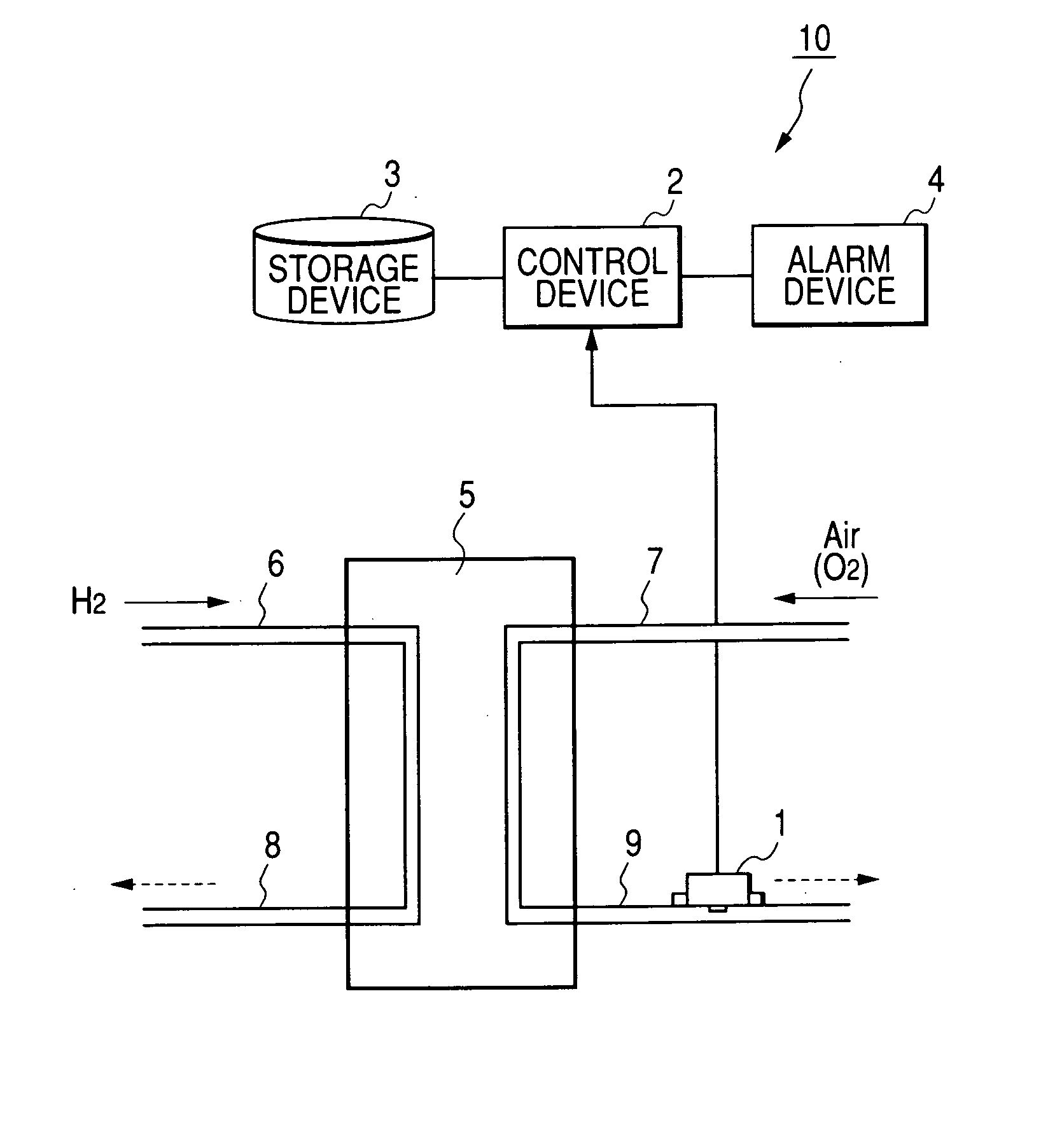
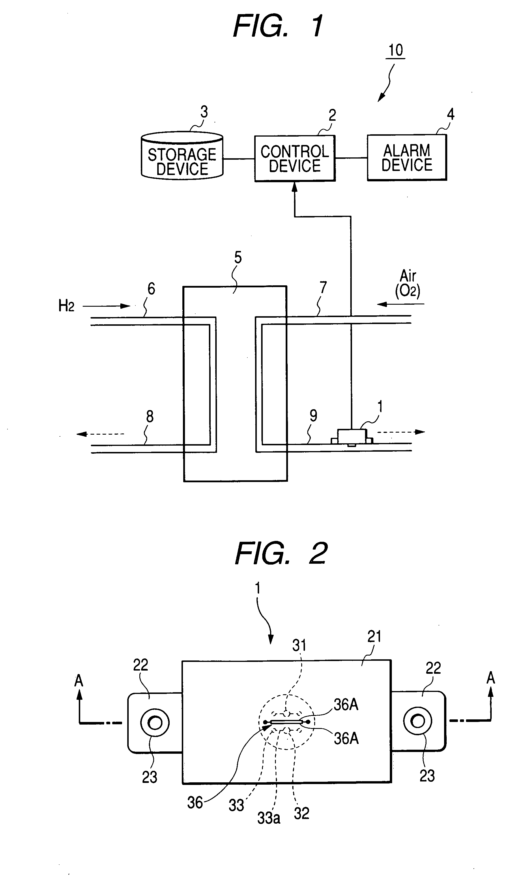
[0039] A gas sensor 1 according to the embodiment constitutes a hydrogen sensor for detecting hydrogen, for example, and is provided on an outlet side piping 9 at an oxygen electrode side and serves to confirm that the hydrogen is not discharged from the outlet side piping 9 in a fuel cell system 10 comprising a control device 2, a storage device 3, an alarm device 4, a fuel cell 5 to be the power source of a vehicle, and pipings 6, 7, 8 and 9 connected to the fuel cell 5 and serving to supply a reaction gas as shown in FIG. 1, for example.

[0040] The control device 2 is connected to the gas sensor 1 attached to the outlet side piping 9 on the oxygen electrode side and decides whether or not the abnormal state of the fuel cell 5 is generated according to the result of a comparison between a detection signal output from the gas senso...


PUM

PropertyMeasurementUnit
electrical resistanceaaaaaaaaaa
current conductanceaaaaaaaaaa
humidityaaaaaaaaaa

Abstract

When the ignition switch of a vehicle is turned OFF, a purging process for increasing the flow of an off-gas fluidizing in each of the outlet side pipings of a fuel cell and discharging water remaining in a fuel cell system to an outside is started to be executed, and the amount of current conductance to the heater of the gas sensor is increased synchronously with the start of the execution of the purging process. With the completion of the purging process, the fluidization of the off-gas in each of the outlet side pipings stops, and the amount of current conductance to each of the units of the gas sensor (for example, an electrifying voltage) is gradually decreased depending on a predetermined current conductance reducing amount which is preset, thereby stopping the current conductance to each of the units and the amount of current conductance to the heater is gradually decreased, thereby stopping the current conductance to the heater.

Description

[0001] This application claims foreign priority based on Japanese Patent application No. 2003-328924, filed September, 2003, the contents of which is incorporated herein by reference in its entirety. BACKGROUND OF THE INVENTION [0002] 1. Field of the Invention [0003] The present invention relates to a control device of a gas sensor such as a contact combustion type hydrogen sensor to be mounted on a fuel cell vehicle. [0004] 2. Description of the Related Art [0005] For example, in the related arts, a solid polymer electrolyte fuel cell comprises a stack (hereinafter referred to as a fuel cell) which is constituted by laminating a plurality of cells on a cell formed by interposing a solid polymer electrolyte membrane between a fuel electrode and an oxygen electrode from both sides. Hydrogen is supplied as a fuel to the fuel electrode and air is supplied as an oxidizing agent to the oxygen electrode, and a hydrogen ion generated by a catalytic reaction at the fuel electrode passes thr...

Claims


Application Information

Patent Timeline
Patent Type & Authority Applications(United States)
IPC IPC(8): G01N27/16H01M8/04
CPCG01N27/16H01M8/04156H01M8/04231H01M8/04462Y02E60/50H01M8/04679H01M8/04738H01M8/04955H01M8/04514
Inventor OISHI, HIDETOSHIINOUE, HIROTOSHISASAKI, TAKASHISAITO, TAKASHI
Owner HONDA MOTOR CO LTD
Why Eureka
Try Eureka