Radiating fin with bent radiating portion and electrothermal oil heater using same

a technology of radiating fin and radiating fin, which is applied in the direction of heating types, lighting and heating apparatus, and domestic stoves or ranges. it can solve the problems of degrading increasing energy consumption and expanding space occupation, and unsatisfactory heat diversion effect, so as to improve the radiating efficiency of the radiator, feel the heat more directly, and strengthen the mechanical strength of the radiating fin

Active Publication Date: 2016-06-30
NINGBO SINGFUN ELECTRIC APPLIANCE
View PDF20 Cites 0 Cited by
  • Summary
  • Abstract
  • Description
  • Claims
  • Application Information

AI Technical Summary

Benefits of technology

[0022]Compared with the prior art, the radiating fin with a bent radiating portion provided by the present invention has the following advantages: by forming a bent radiating portion within a region, a certain distance away from the middle, of an edge of any end of the radiating fin, the radiating area of the radiating fin is increased and the mechanical strength of the radiating fin is strengthened; and when a plurality of the radiating fins are connected to each other, a combined radial and convective radiating way may be realized and meanwhile the transverse radiation and the longitudinal radiation of the radiator are strengthened, so that a user may feel the heat more directly. Such a structure may further prevent the surface temperature of the radiator from being too high, the heat radiation of the radiator to the surrounding is more uniform, and the radiating efficiency of the radiator is improved.

Problems solved by technology

However, such a radiating fin has a limited radiating area and small heat supply range, and hence, the heat diversion effect is not very ideal.
Merely increasing the superficial area of the radiating fin will increase energy consumption and expand space occupation, and also will degrade the mechanical strength of the radiating fin.
Consequently, the temperature interior of the oil heater is too high and the service life of the oil heater will be shortened.

Method used


Image

  • Radiating fin with bent radiating portion and electrothermal oil heater using same
  • Radiating fin with bent radiating portion and electrothermal oil heater using same
  • Radiating fin with bent radiating portion and electrothermal oil heater using same

Examples


embodiment 1

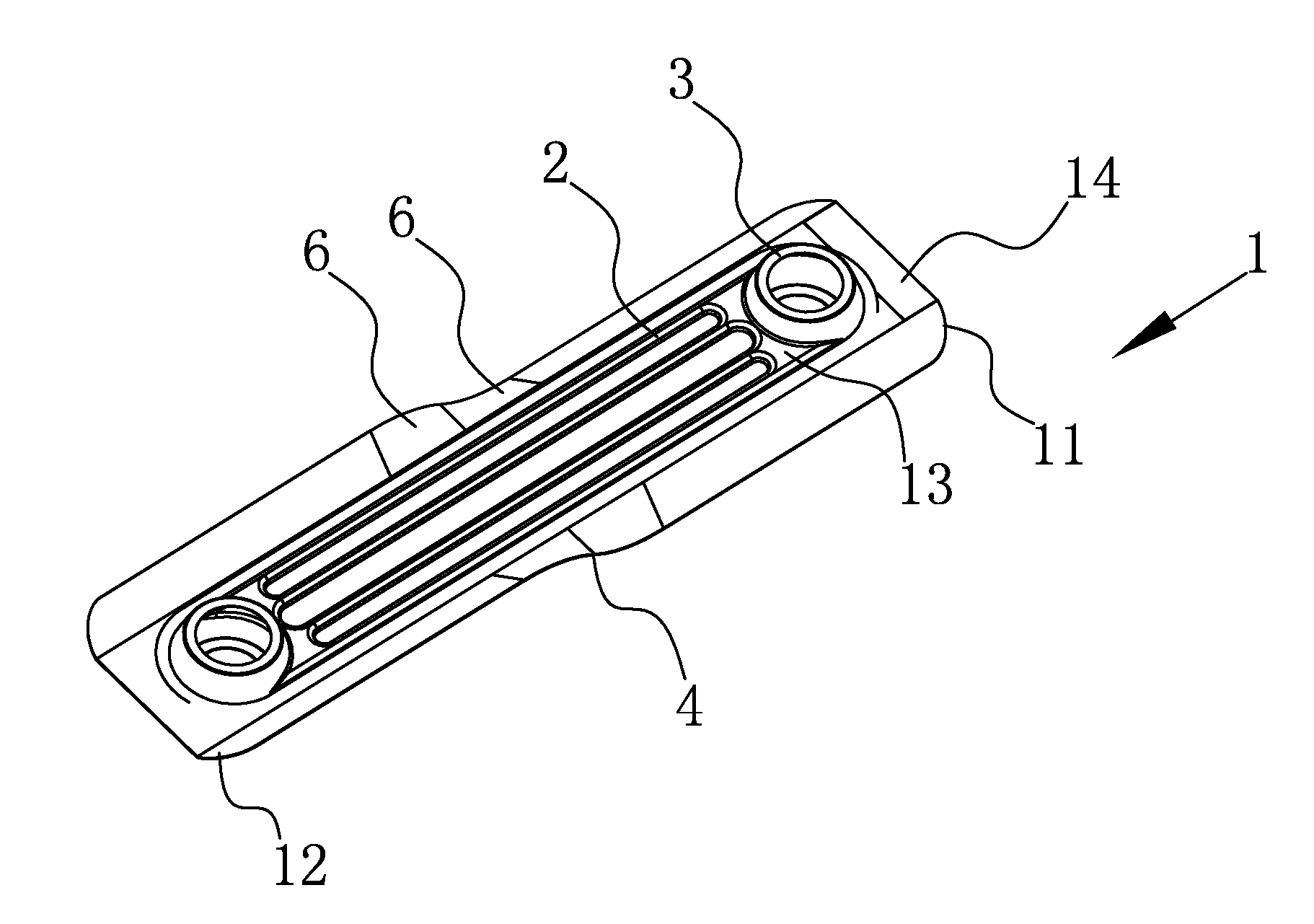
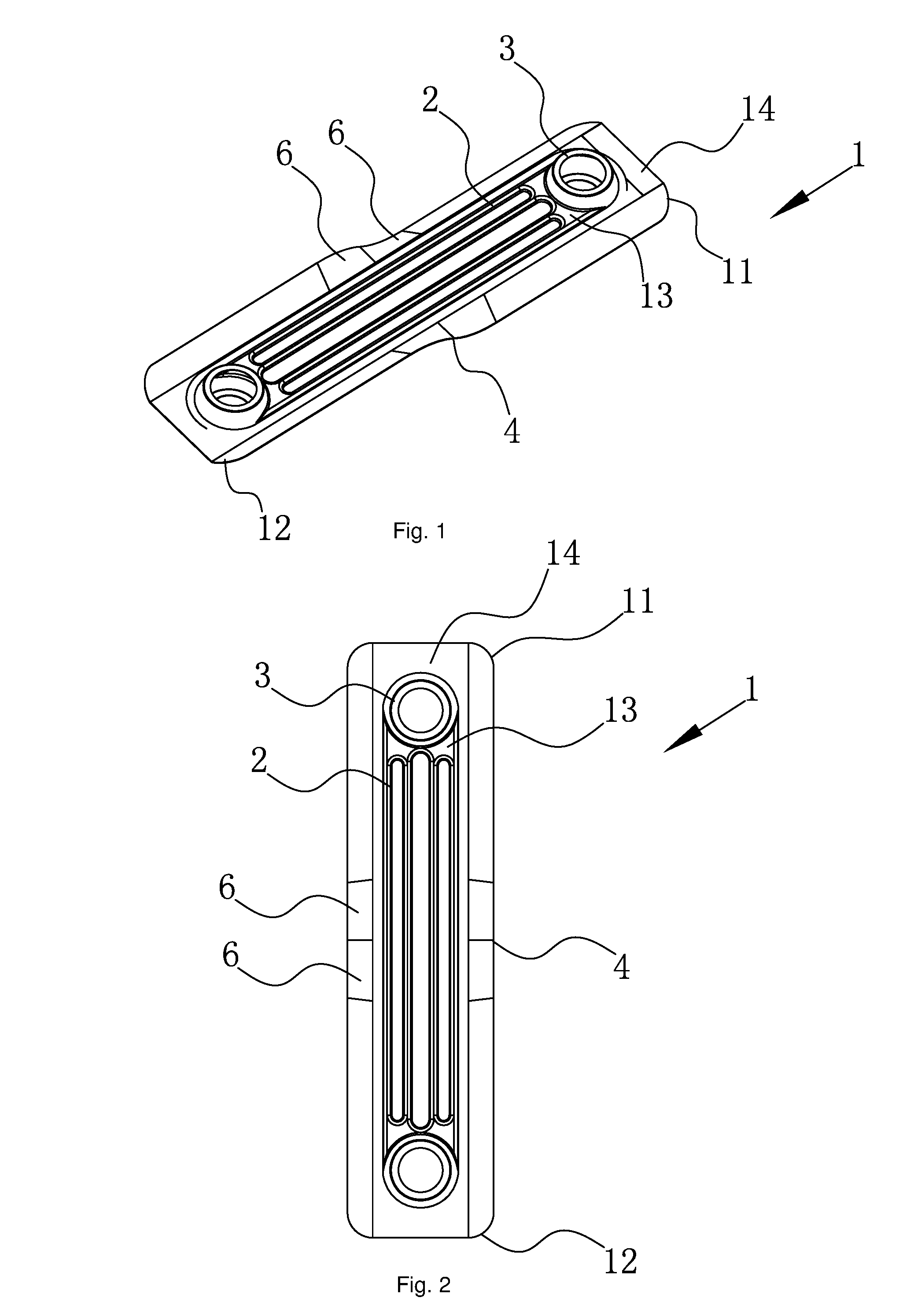
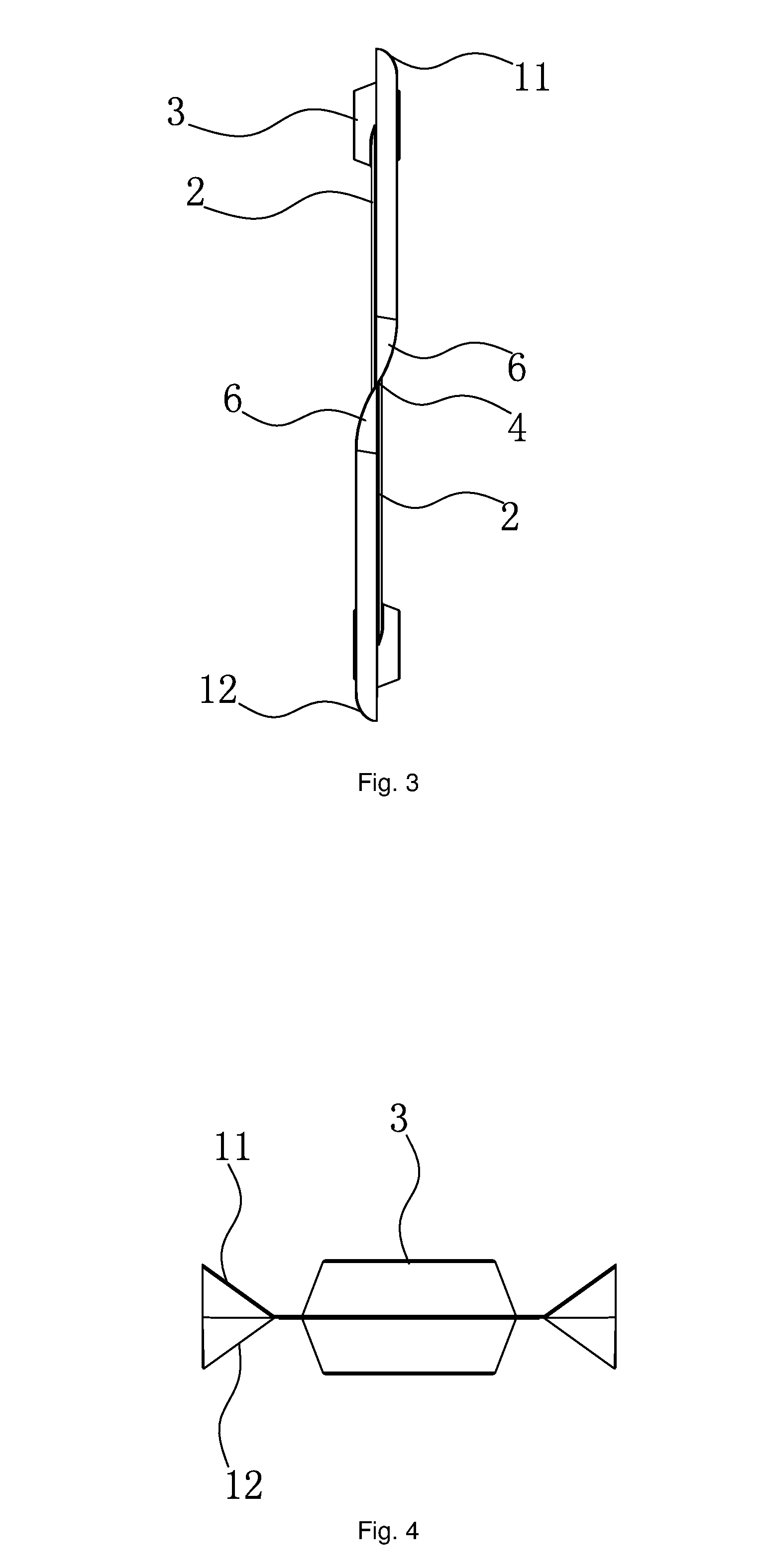
[0042]Referring to FIG. 1 to FIG. 6, according to this embodiment of the radiating fin with a bent radiating portion provided by the present invention, the radiating fin includes a main body 1 with an oil guide groove 2 formed therein, connecting sleeves 3 extending in a horizontal direction are provided at an upper end 11 and a lower end 12 of the main body 1; a bent radiating portion is formed within a region, a certain distance away from the middle, of an edge of at least one end of the main body 1; and an upper end 11 and a lower end 12 of the bent radiating portion are located in different vertical planes and connected to each other by a twist portion 4, the twist portion 4 including two bending portions 6 in opposite directions. By forming a bent radiating portion within a region, a certain distance away from the middle, of an edge of any end of the radiating fin, the radiating area of the radiating fin is increased and the mechanical strength of the radiating fin is strengthe...

embodiment 2

[0051]Referring to FIG. 7 to FIG. 12, this embodiment is roughly the same as the aforementioned embodiment 1, with the difference in that the upper end 11 and the lower end 12 of the bent radiating portion in this embodiment are located in a same vertical plane and connected to each other by a bent portion 5, the bent portion 5 including two bending portions 6 in a same direction. An included angle between a vertical projection of the upper end and the lower end and a vertical projection of the bent portion is 5° to 85°, and preferably 36° in this embodiment. This angle may ensure the convection of upper ends and the lower ends of two adjacent radiating fins, without damaging the twisted portion. A distance from an apex of the bent portion 5 to the plane of the upper end and the lower end is 5 mm to 70 mm, and preferably 20 mm in this embodiment. By forming a bent radiating portion within a region, a certain distance away from the middle, of an edge of any end of the radiating fin, ...

embodiment 3

[0052]Referring to FIG. 13 to FIG. 18, this embodiment is roughly the same as the aforementioned embodiment 1, with the difference in that the upper end 11 and the lower end 12 of the bent radiating portion in this embodiment are located in a same vertical plane and connected to each other by a plurality of bent portions 5, two adjacent bent portions 5 are bent in opposite directions, and each of the bent portions 5 includes two bending portions 6 in a same direction. An included angle between a vertical projection of the upper end and the lower end and a vertical projection of the bent portion is 5° to 85°, and preferably 36° in this embodiment. This angle may ensure the convection of upper ends and the lower ends of two adjacent radiating fins, without damaging the twisted portion. A distance from an apex of the bent portion to the plane of the upper end and the lower end is 5 mm to 70 mm, and preferably 20 mm in this embodiment. By forming a bent radiating portion within a region...


PUM


Abstract

A radiating fin with a bent radiating portion and an electrothermal oil heater using the same are provided. The radiating fin comprises a main body with an oil guide groove formed therein, connecting sleeves extending in a horizontal direction being provided at an upper end and a lower end of the main body; a bent radiating portion is formed within a region, a certain distance away from the middle, of an edge of at least one end of the main body; and an upper end and a lower end of the bent radiating portion are located in different vertical planes, or the upper end and the lower end of the bent radiating portion are located in a same vertical plane, and at least one portion between the upper end and the lower end is bent to form a side-raised structure. Compared with the prior art, the radiating fin with a bent radiating portion provided in the present invention has the following advantages: by forming a bent radiating portion within a region, a certain distance from the middle, of an edge of any end of the radiating fin, when a plurality of the radiating fins are connected to each other, a combined radial and convective radiating way can be realized and meanwhile the transverse radiation and the longitudinal radiation of the radiator are strengthened.

Description

TECHNICAL FIELD[0001]The present invention relates to a radiating fin, in particular to a radiating fin with a bent radiating portion, and the present invention further relates to an electrothermal oil heater using the same.BACKGROUND ART[0002]Oil-filled electrothermal warmers are referred to as electrothermal oil heaters now. The electrothermal oil heaters, as environmentally friendly, noiseless and other advantages, have been widely used in the world. There are 40 million electrothermal oil heaters manufactured every year. Such an electrothermal oil heater is generally assembled by a plurality of radiating fins, with gaps formed between the radiating fins, connected to each other via hollow connecting sleeves at an upper end and a lower end of the radiating fins. There is a cavity, filled with heat transfer oil, formed on each of the radiating fins. An electrical heating assembly is immersed in the heat transfer oil, and energy is transferred by heating the heat transfer oil. Howe...

Claims


Application Information

Patent Timeline
Patent Type & Authority Applications(United States)
IPC IPC(8): F28F3/06F24H3/00F28F3/08
CPCF28F3/06F24H3/004F28F3/083F24D19/008F28D1/0226F24D13/04F28D1/0333F28D1/05358F28D2021/0035F28F3/048F28F3/12F24H3/00
Inventor YAO, GUONINGMAO, JIALEI
Owner NINGBO SINGFUN ELECTRIC APPLIANCE
Why Eureka
Try Eureka