Method of manufacturing optical fiber base material and apparatus therefor

a technology of optical fiber and base material, which is applied in the direction of manufacturing tools, glass deposition burners, instruments, etc., can solve the problems of affecting the density and refractive index profile of soot in the axial direction and affecting the performance of the base material

Active Publication Date: 2007-10-25
SHIN ETSU CHEM IND CO LTD
View PDF8 Cites 1 Cited by
  • Summary
  • Abstract
  • Description
  • Claims
  • Application Information

AI Technical Summary

Benefits of technology

[0013] Thus, an advantage of the present invention is to provide a manufacturing method for acquiring an optical fiber base material having a stable refractive index profile by constantly keeping the relative position between the burner and the soot deposition and an apparatus therefor. Particularly, an advantage of the present invention is to provide a manufacturing method for stabilizing the position of the burner after the relative position between the burner and the soot deposition is adjusted without changing over time during depositing the soot and an apparatus therefor.
[0014] To obtain the above-described advantages, a first aspect of the present invention provides a method of manufacturing an optical fiber base material comprising depositing soot generated by flame hydrolysis by using a burner which generates a flame to compound the optical fiber base material. The fluctuation band of the surface temperature of a burner fixing section that positions the burner is kept equal to or less than 80 degree C. Here, it is preferred that the fluctuation band is lesser, of couse, and particularly, the refractive index profile of the resultant optical fiber base material is sufficiently stabilized if the fluctuation band is equal to or less than 80 degree C. as described in detail later.
[0015] In addition, according to an embodiment, the temperature of the burner fixing section is controlled by a temperature control mechanism in the manufacturing method. Thereby mechanism that keeps the fluctuation band of the surface temperature of the burner fixing section can be provided.
[0016] Moreover, according to another embodiment, the burner fixing section includes a burner holder and a fixture thereof, and the temperature control mechanism includes a heat shield plate arranged between the burner flame and at least one of the burner holder and the fixture in the manufacturing method. Thereby the radiant heat of the burner flame is shielded, so that the surface temperature of the burner fixing section can be prevented from being changed.
[0017] According to further another embodiment, the temperature control mechanism includes at least one of a temperature control mechanism that heats the burner fixing section and a temperature control mechanism that cools the burner fixing section in the manufacturing method. Here, the “temperature control” may include “heating”, “cooling” and “keeping the temperature”. “Heating” may include directly or indirectly heating with such as an electric heater. “Cooling” may include cooling with refrigerant. Thereby the surface temperature of the burner fixing section can be kept within a predetermined range.
[0018] A second aspect of the present invention provides, in a method of manufacturing an optical fiber base material including a step of depositing soot generated by flame hydrolysis by using a burner which generates a flame to compound an optical fiber base material, a manufacturing apparatus including a temperature control mechanism that keeps the fluctuation band of the surface temperature of a burner fixing section which positions the burner equal to or less than 80 degree C. Here, it is preferred that the fluctuation band is lesser, of course, and particularly, the refractive index profile of the resultant optical fiber base material is sufficiently stabilized if the fluctuation band is equal to or less than 80 degree C. and the amount of fluctuation of all over the optical fiber base material is not beyond the predetermined bounds of permissibility.

Problems solved by technology

Then, a problem has been generated that the burner is displaced and the fixed portion is loosed because the burner and the burner fixing section are thermally expanded due to the heat cycle for which the soot is deposited and the deposition is stopped so that the relative positional between the burner and the soot deposition is displaced.
Moreover, another problem has been generated due to the displacement that the sticking rate, the density and the refractive index profile of the soot in the axial direction of the base material are changed.

Method used


Image

  • Method of manufacturing optical fiber base material and apparatus therefor
  • Method of manufacturing optical fiber base material and apparatus therefor
  • Method of manufacturing optical fiber base material and apparatus therefor

Examples


embodiment 1

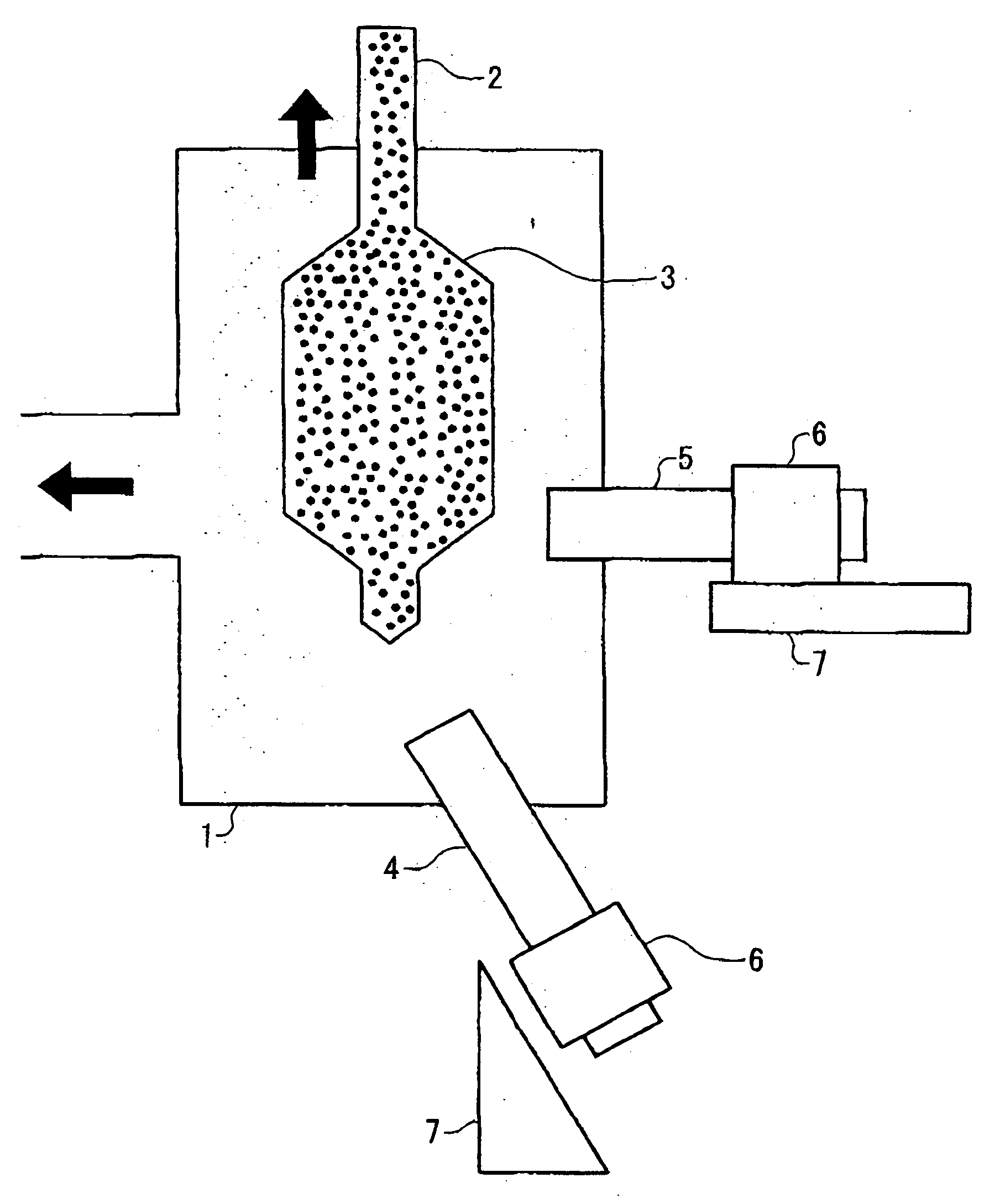
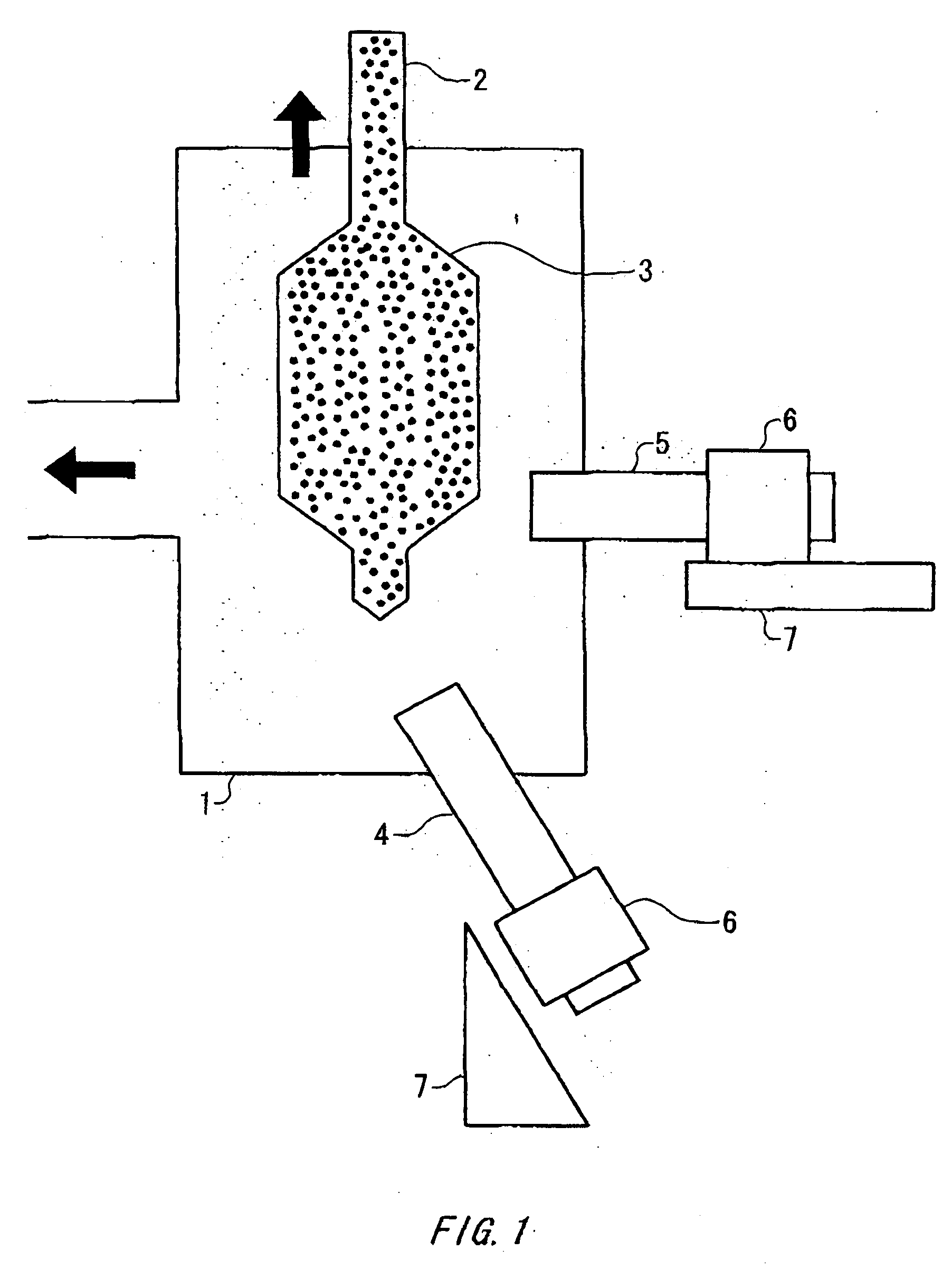
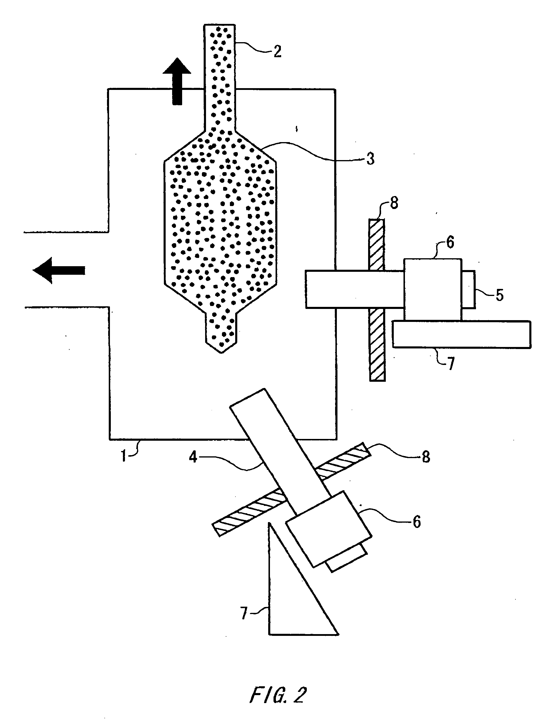
[0030] The soot deposition 3 is manufactured by using an apparatus shown in FIG. 2. Here, the components in FIG. 2 the same as those in FIG. 1 have the reference numerals the same as those of FIG. 1, so that the repeated description is omitted.

[0031] The apparatus shown in FIG. 2 has a heat shield plate 8 made of SUS, which is arranged between a burner fixing section including a burner holder 6 and a fixture 7, and burner flame. Thereby the burner fixing section is shielded from the radiant heat of the burner flame. Here, an effect on the refractive index distribution of the soot deposition 3 due to shielding the radiant heat of the burner flame is tested by using two kinds of SUS plates having the size of 100×100×5 mm and the size of 150×150×5 mm, respectively as the heat shield plate 8.

[0032] The soot deposition 3 is manufactured by supplying silicon tetrachloride (SiCl4) and germanium tetrachloride (GeCl4) being core materials along with H2 gas and O2 gas for oxyhydrogen flame ...

embodiment 2

[0035] The optical fiber base material is manufactured with the material and under the condition the same as those of the embodiment 1 except for using the manufacturing apparatus shown in FIG. 4. Here, the components in FIG. 4 the same as those in FIG. 1 and FIG. 2 have the reference numerals the same as those of FIG. 1 and FIG. 2, so that the repeated description is omitted.

[0036] In the manufacturing apparatus, the burner fixing section including the burner holder 6 and the fixture 7 is stored in a temperature-controlled box 9 to keep the temperature within 60 degree C.±1 degree C. The refractive index profile of the resultant optical fiber base material obtained by transparently vitrifying is measured and the measurement result is indicated by a graph in FIG. 5. The fluctuation of the refractive index profile is significantly reduced as shown in the figure


PUM

PropertyMeasurementUnit
refractive indexaaaaaaaaaa
sizeaaaaaaaaaa
sizeaaaaaaaaaa

Abstract

In a method of manufacturing an optical fiber base material including depositing soot generated by flame hydrolysis, the fluctuation band of the surface temperature of a burner fixing section including a burner holder and its fixture for burners for compounding the optical fiber base material is kept equal to or less than 80 degree C. The temperature can be controlled by a heat shield plate arranged between a burner flame and a burner fixing section and a temperature control mechanism that heats or cools the burner fixing section. Thereby the relative position between the burner and the soot deposition is stabilized, so that the manufacturing method being capable of manufacturing an optical fiber base material having a stable refractive index and the apparatus therefor can be provided.

Description

CROSS REFERENCE TO RELATED APPLICATION [0001] This is a continuation application of PCT / JP2005 / 009324 filed on May 23, 2005 which claims priority from a Japanese Patent Application No. 2004-288177 filed on Sep. 30, 2004, the contents of which are incorporated herein by reference. BACKGROUND [0002] 1. Technical Field [0003] The present invention relates to a method of manufacturing an optical fiber base material and an apparatus therefor. Specifically, the present invention relates to a manufacturing method applicable to manufacture an optical fiber material by utilizing flame hydrolysis and a manufacturing apparatus therefor. [0004] 2. Related Art [0005] A manufacturing apparatus by using the VAD method has been known as an apparatus for manufacturing an optical fiber base material. In that apparatus, a quartz base material 2 is suspended in a quartz chamber 1 as shown in FIG. 1, and soot is deposited the quartz base material 2 to acquire a soot deposition 3. A core burner 4 toward ...

Claims


Application Information

Patent Timeline
Patent Type & Authority Applications(United States)
IPC IPC(8): C23C16/26
CPCC03B37/0142C03B2207/60C03B2207/50C03B2207/42C03B19/14C03B37/018G02B6/00
Inventor YOSHIDA, MAKOTO
Owner SHIN ETSU CHEM IND CO LTD
Why Eureka
Try Eureka