Device for load transfer

Active Publication Date: 2022-06-21
M W B
View PDF33 Cites 0 Cited by
  • Summary
  • Abstract
  • Description
  • Claims
  • Application Information

AI Technical Summary

Benefits of technology

[0027]The height of the contact on the support frame is advantageously adjustable and can be adjusted relative to the support frame of the trailer-train trailer by means of a lifting mechanism. By lowering the contact relative to the support frame that is provided with the continuous conveyor, it is thereby possible in a simple matter to connect the contact of the trailer-train trailer that is connected with the battery of the trailer train with the contact of the stationary transfer station to drive the motor of the additional continuous conveyor of the transfer station with current from the battery of the trailer train. In the predetermined handling position, as the contact, in particular a switch contact, of the contact that is connected with the battery of the trailer-train trailer is lowered, it strikes the contact of the transfer station and thereby closes the circuit for the power supply of the additional motor of the additional continuous conveyor on the transfer station. With at least one height-adjustable contact of the trailer-train trailer located on the support frame which is in connection with the battery of the trailer train, and a corresponding mating contact on the stationary transfer station it is thereby possible in a simple manner, when the handling position is reached and the contact of the trailer-train trailer that is in connection with the battery o

Problems solved by technology

A continuous conveyor that can be moved in the transverse direction of the trailer-train trailer by means of a sled, however, requires a high level of construction effort and expense on the trailer-train trailer.
However, the need to connect the power supply of the additional motor of the transfer station that drives the continuous conveyor of the transfer station to the power network of a building has the disadvantage that in the event of a change in the installation location of the stationary tran

Method used


Image

  • Device for load transfer
  • Device for load transfer
  • Device for load transfer

Examples


Embodiment Construction

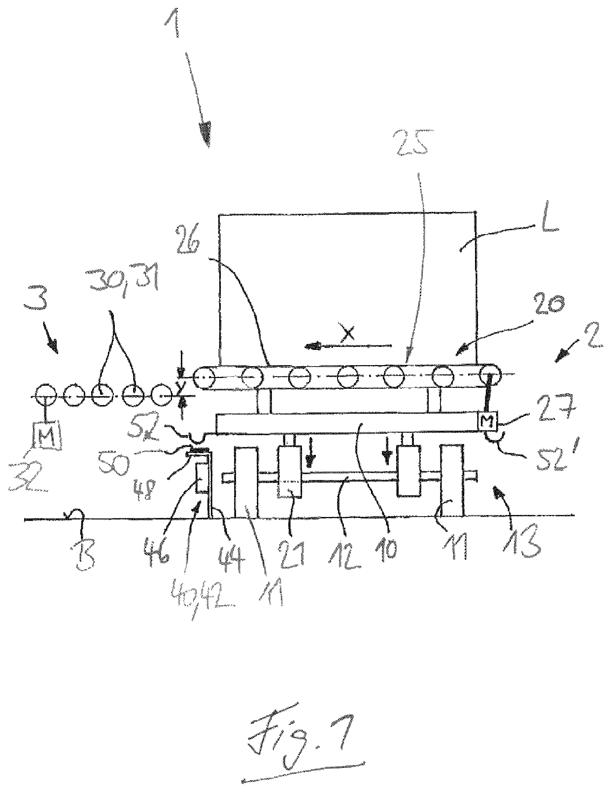
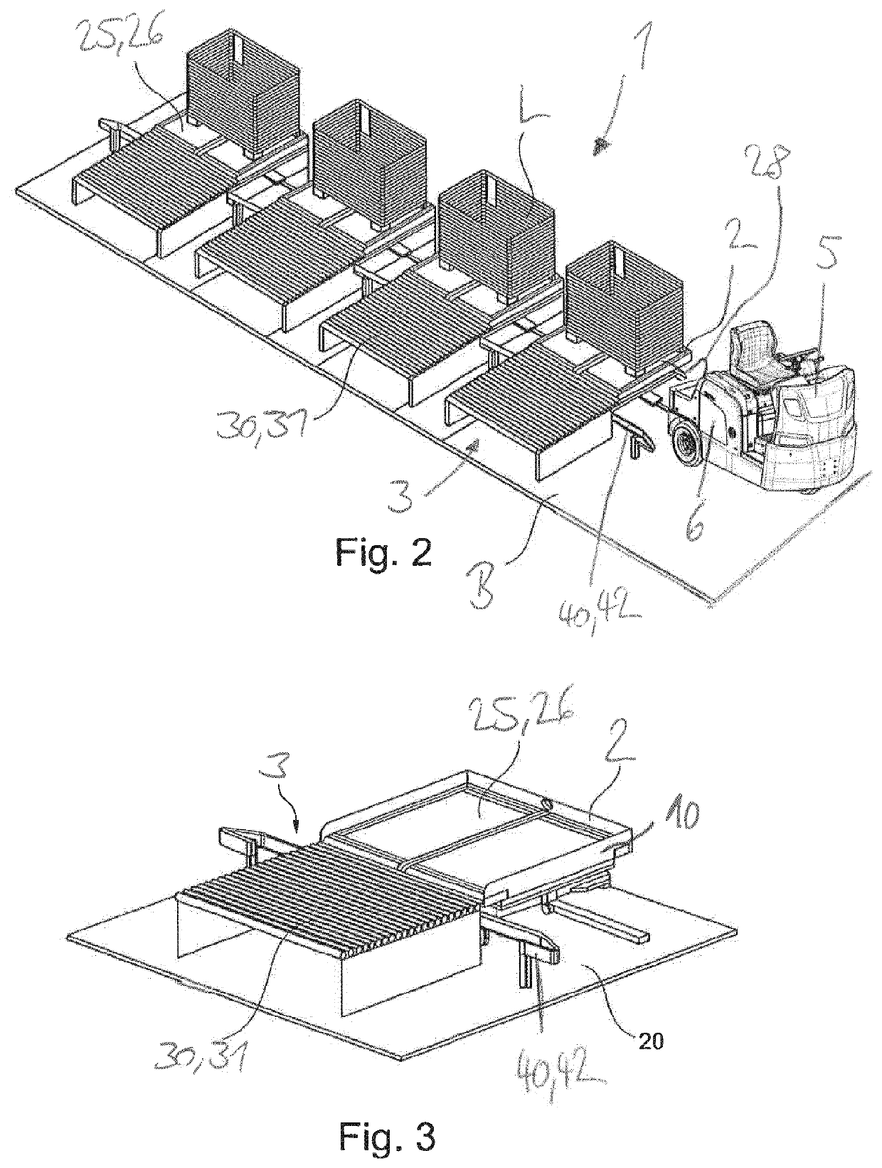
[0042]The device according to the disclosure illustrated in FIGS. 1 to 11 is explained below on the basis of the example of a trailer train 1 with at least one trailer-train trailer 2, whereby a load L such as a pallet or a mesh box for example is to be transferred from a trailer-train trailer 2 of the trailer train 1 in the x direction (transverse direction of the trailer-train trailer 2) to a stationary transfer station 3 or in the opposite direction from the stationary transfer station 3 to the trailer-train trailer 2 of the trailer train 1.

[0043]The trailer train 1—as illustrated in FIG. 2—has a tractor vehicle 5 which is provided with a battery 6. The tractor vehicle 5 has a battery-powered electrical drive system with an electric traction drive, whereby the battery 6 is preferably in the form of a traction battery that powers the traction drive of the tractor vehicle 5.

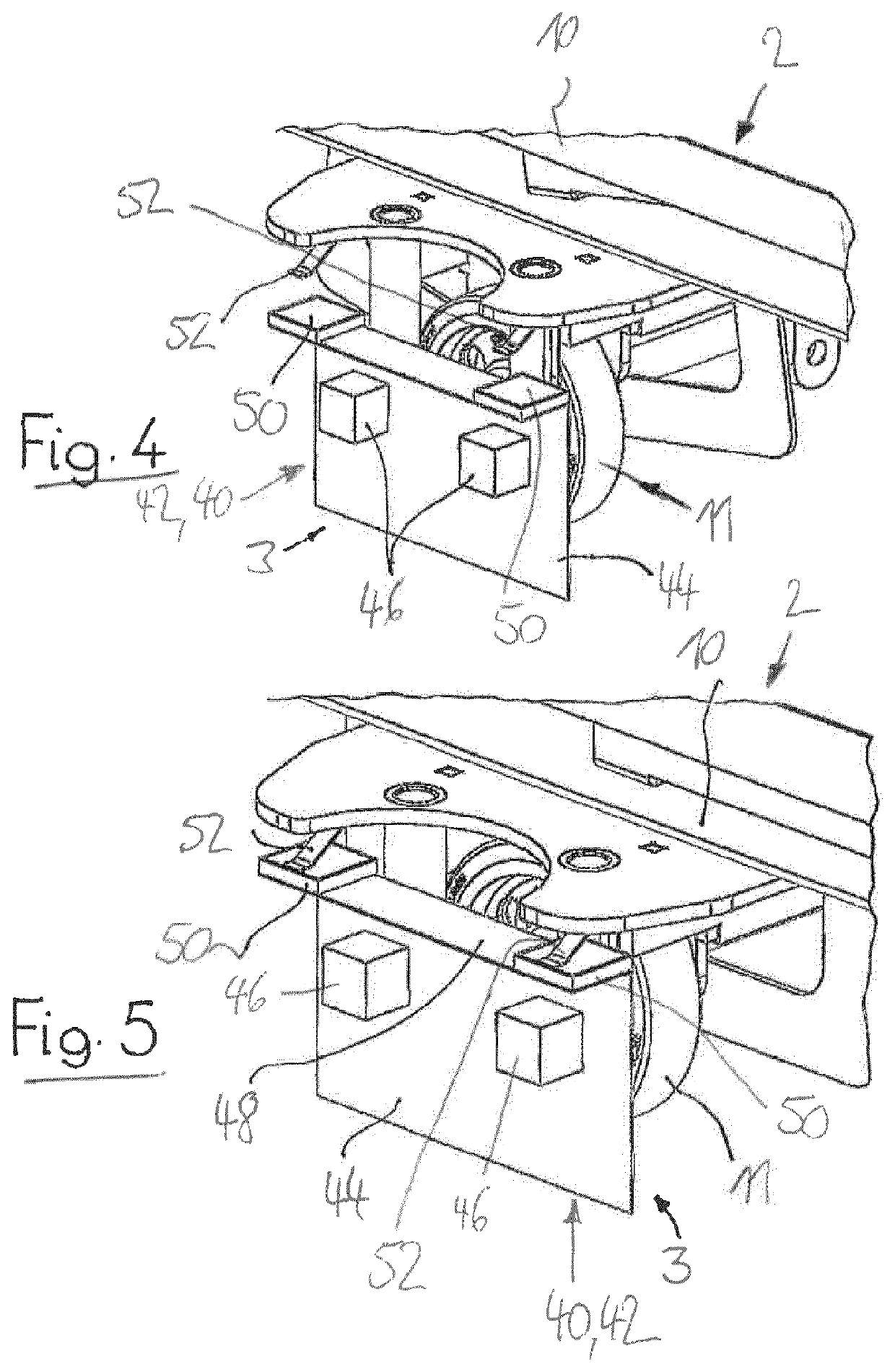
[0044]As shown by the exemplary embodiment illustrated in FIGS. 1 to 5 and the exemplary embodiment illustrat...


PUM


Abstract

The invention relates to a device comprising a stationary transfer station (3) and a trailer train (1) comprising at least one trailer-train trailer (2), for transferring loads (L) from the trailer-train trailer (2) into the stationary transfer station (3), the trailer-train trailer (2) being provided with a continuous conveyor (25) driven by a motor (27), for receiving the load (L). The motor (27) of the continuous conveyor (25) of the trailer-train trailer (2) is powered by a battery (6) of the trailer train (1). Another continuous conveyor (30) driven by another motor (32) is arranged in the transfer station (3), for receiving the load (L), the other motor (32) of the other continuous conveyor (30) being powered in the transfer station (3) in a pre-determined handling position by the battery (6) of the trailer train (1).

Description

CROSS REFERENCE TO RELATED APPLICATIONS[0001]This application is the United States national phase of International Application No. PCT / EP2018 / 072500 filed Aug. 21, 2018, and claims priority to German Patent Application No. 10 2017 122 704.0 filed Sep. 29, 2017, the disclosures of which are hereby incorporated by reference in their entirety.BACKGROUND OF THE INVENTIONField of the Invention[0002]The disclosure relates to a device including a stationary transfer station and a trailer train including at least one trailer-train trailer for transferring loads from the trailer-train trailer into the stationary transfer station, the trailer-train trailer being provided with a motor-driven continuous conveyor for receiving the load.Description of Related Art[0003]For the transport of loads, for example pallets or mesh boxes designed to hold loads, within a plant, increasing use is being made of trailer trains, the trailer-train trailers of which are transported to the desired transfer statio...

Claims


Application Information

Patent Timeline
IPC IPC(8): B60P1/38B60R16/033B65G37/00B65G65/00
CPCB60P1/38B60R16/033B65G37/005B65G65/005B65G2203/042B65G2814/0352B65G65/00B60P1/52B62D53/005
Inventor BERGHAMMER, FRITZ
Owner M W B
Why Eureka
Try Eureka