Tool for stabilizing a position of a shaft

a technology for stabilizing tools and shafts, which is applied in the direction of manufacturing tools, portable power-driven tools, light applications, etc., can solve the problems of unintended forces being radially applied to the bearings that support the shaft, wear in the bearings, and the performance and service life of the bearings could deteriora

Inactive Publication Date: 2018-12-13
SOLAR TURBINES
View PDF6 Cites 0 Cited by
  • Summary
  • Abstract
  • Description
  • Claims
  • Application Information

AI Technical Summary

Benefits of technology

[0006]In an aspect of the present disclosure, a tool is provided for stabilizing a position of a shaft that could be disposed within a casing and rotatably supported by a pair of bearings. The bearings may be spaced-apart from one another within the casing. The tool includes an arcuately-shaped shoe that is located between the pair of bearings and releasably connected to the casing. The shoe has a concave surface defining a radius corresponding to a radius of the shaft. The shoe is resiliently biased away from the casing for facilitating the concave surface of the shoe to radially abut with a portion of an outer circumference of the shaft.

Problems solved by technology

Such displacement of the shaft from its initial position during transportation of the machine could cause unintended forces to be radially applied to the bearings that support the shaft.
These forces may cause wear in the bearings.
Subsequently, a performance and service life of the bearings could deteriorate, in operation, if the shaft moves from its initial position.
This makes the collar member of the '263 patent bulky in construction.
Therefore, the collar member may occupy a large amount of space that may not always be available in machines owing to various space constraints.

Method used


Image

  • Tool for stabilizing a position of a shaft
  • Tool for stabilizing a position of a shaft
  • Tool for stabilizing a position of a shaft

Examples


Embodiment Construction

[0021]Reference numerals appearing in more than one figure indicate the same or corresponding parts in each of them. References to elements in the singular may also be construed to relate to the plural and vice-versa without limiting the scope of the disclosure to the exact number or type of such elements unless set forth explicitly in the appended claims.

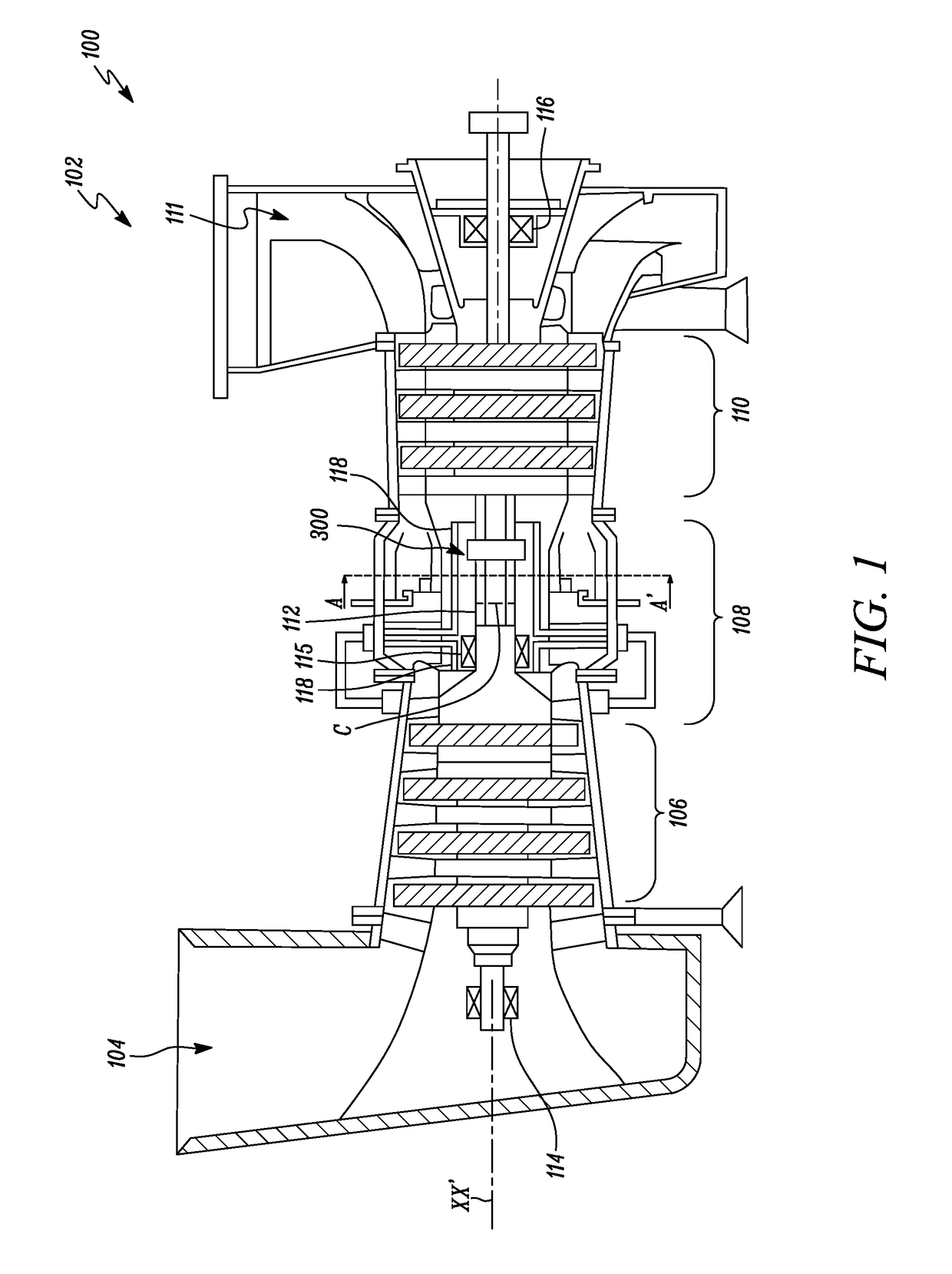
[0022]FIG. 1 illustrates a sectional view of a machine 100. As shown in FIG. 1, the machine 100 is embodied in the form of a gas turbine engine 102. The gas turbine engine 102 may be of any type. In one embodiment, the gas turbine engine 102 may be an industrial turbine engine including, but not limited to, an axial flow turbine used for power generation or driving mechanical assemblies. In other embodiments, the gas turbine engine 102 may be of a type that is typically used in jet propulsion systems. As shown in FIG. 1, the gas turbine engine 102 may embody an axial flow industrial turbine which may be used for power generation.

[0...


PUM


Abstract

A tool is provided for stabilizing a position of a shaft disposed within a casing and rotatably supported by a pair of bearings that are spaced-apart from one another and located within the casing. The tool includes an arcuately-shaped shoe that is located between the pair of bearings and releasably connected to the casing. The shoe has a concave surface defining a radius corresponding to a radius of the shaft. The shoe is resiliently biased away from the casing for facilitating the concave surface of the shoe to radially abut with a portion of an outer circumference of the shaft.

Description

TECHNICAL FIELD[0001]The present disclosure relates to a tool for stabilizing a position of a shaft. More particularly, the present disclosure relates to a tool for stabilizing a position of a shaft during transportation of a machine in which the shaft is rotatably supported.BACKGROUND[0002]Many machines are known to include a shaft for rotatively transmitting power from one component to another. For example, turbomachines such as gas turbine engines may include a turbine and a shaft for rotating the turbine. In many cases, these machines may need to be transported from one location to another. In such cases, the shaft, which would be typically supported on a pair of bearings within a housing of the machine, could be displaced from its initial position that is established during assembly of the machine. Such displacement of the shaft from its initial position during transportation of the machine could cause unintended forces to be radially applied to the bearings that support the sh...

Claims


Application Information

Patent Timeline
Patent Type & Authority Applications(United States)
IPC IPC(8): B24B23/02B25F5/02F16C41/04
CPCB24B23/02B25F5/028B25F5/001F16C41/045F16C41/04F16C2362/00
Inventor LUCKETT, THOMAS MICHAELROCKLAGE, JOSHUA MICHAELACUNA, ANTONIOCHANDRASEKAR, JAGADEESHKASHI, ASHWINKUMAR SURESH
Owner SOLAR TURBINES
Why Eureka
Try Eureka