Damper structure for clutch

Active Publication Date: 2015-12-03
KAWASAKI MOTORS LTD
View PDF8 Cites 0 Cited by
  • Summary
  • Abstract
  • Description
  • Claims
  • Application Information

AI Technical Summary

Benefits of technology

[0007]An object of the present invention is to provide a damper structure, for clutches, which allows a deformatio

Problems solved by technology

However, in a case where an axial clearance between the damper and the driven-side rotary member is increased so as to assuredly obtain such a deformation margin, an axial position of the damper is rendered to be unstable.
Further, in a case where the axial clearance is increased, the outer circumferential surface of the damper to be pressed by a clutch gear of the drivin

Method used


Image

  • Damper structure for clutch
  • Damper structure for clutch
  • Damper structure for clutch

Examples


Example

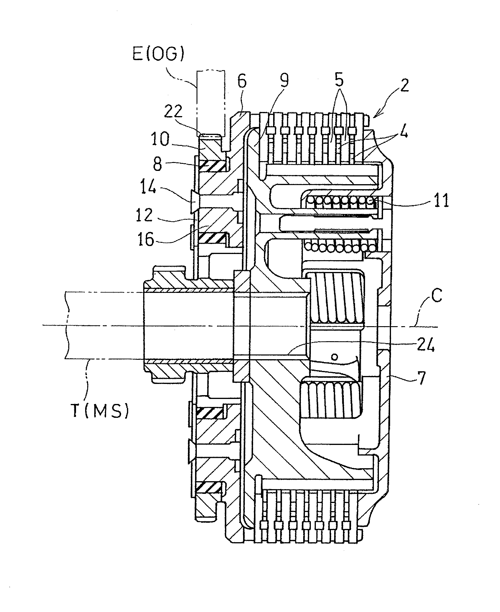
[0026]Hereinafter, a preferred embodiment of the present invention will be described with reference to the drawings. FIG. 1 is a cross-sectional view of a clutch having a damper structure according to a preferred embodiment of the present invention.

[0027]A clutch 2 is in the form of a friction plate clutch, and is disposed between an engine E and a transmission T of a vehicle such as a motorcycle, so as to connect or disconnect power, of the engine E, to be transmitted to the transmission T. More specifically, the clutch 2 having a clutch gear 10 is mounted to a main shaft MS of the transmission T, and the clutch gear 10 meshes with an output gear OG mounted to a rotation shaft of the engine E. The main shaft MS is spline-fitted to an output tooth portion 24 of the clutch 2, and is connected to the clutch 2 so as not to rotate relative to each other.

[0028]A clutch housing 6 is connected to the clutch gear 10 of the clutch 2 via a damper 8, and a plurality of friction plates 5 are su...


PUM


Abstract

A clutch includes a clutch housing configured to hold a clutch plate, and a clutch gear configured to transmit rotary drive power to the clutch housing via a damper. The clutch housing has a rib that regulates a position, of the damper, in an axial direction. The dampers are accommodated in accommodation holes that are spaced from each other in a circumferential direction of the clutch gear. The rib is formed in an annular shape so as to be aligned with the accommodation holes.

Description

CROSS REFERENCE TO THE RELATED APPLICATION[0001]This application is based on and claims Convention priority to Japanese patent application No. 2014-111344, filed May 29, 2014, the entire disclosure of which is herein incorporated by reference as a part of this application.BACKGROUND OF THE INVENTION[0002]1. Field of the Invention[0003]The present invention relates to a damper structure of clutches for use in internal combustion engines for vehicles, mainly for saddle-riding type vehicles such as motorcycles, three-wheeled vehicles, and four-wheeled buggies.[0004]2. Description of Related Art[0005]As clutches for use in internal combustion engines of vehicles, it has been known that a clutch that has a damper, for damping torque, is interposed between a driving-side rotary member and a driven-side rotary member, and absorbs variation in torque that is generated in a power transmission system for an internal combustion engine (for example, JP Examined Utility Model Publication No. 03-...

Claims


Application Information

Patent Timeline
IPC IPC(8): F16D13/58F16D13/52
CPCF16D13/58F16D2300/22F16D13/52F16D2300/26F16F15/136
Inventor INAGAKI, YOSHIHIKONAKAMURA, YASUSHI
Owner KAWASAKI MOTORS LTD
Why Eureka
Try Eureka