One-way clutch

a one-way clutch and clutch technology, applied in the field of one-way clutches, can solve problems such as possible increase in assembly errors

Active Publication Date: 2017-06-22
JTEKT CORP
View PDF15 Cites 0 Cited by
  • Summary
  • Abstract
  • Description
  • Claims
  • Application Information

AI Technical Summary

Benefits of technology

[0011]An object of the invention is to stabilize, in a one-way clutch, positioning of a cage with respect to an inner ring.

Problems solved by technology

However, in this case, the position of the cage 93 in the axial direction fails to be constant due to the magnitude of a load imposed on the cage 93 to move the cage 93 and an error in production accuracy (inclination angle) of the inclined surfaces 98a. The positioning of the cage 93 (the rollers 92 held by the cage 93) with respect to the inner ring 90 is unstable, leading to a possible increase in assembly error.

Method used


Image

  • One-way clutch
  • One-way clutch
  • One-way clutch

Examples


Embodiment Construction

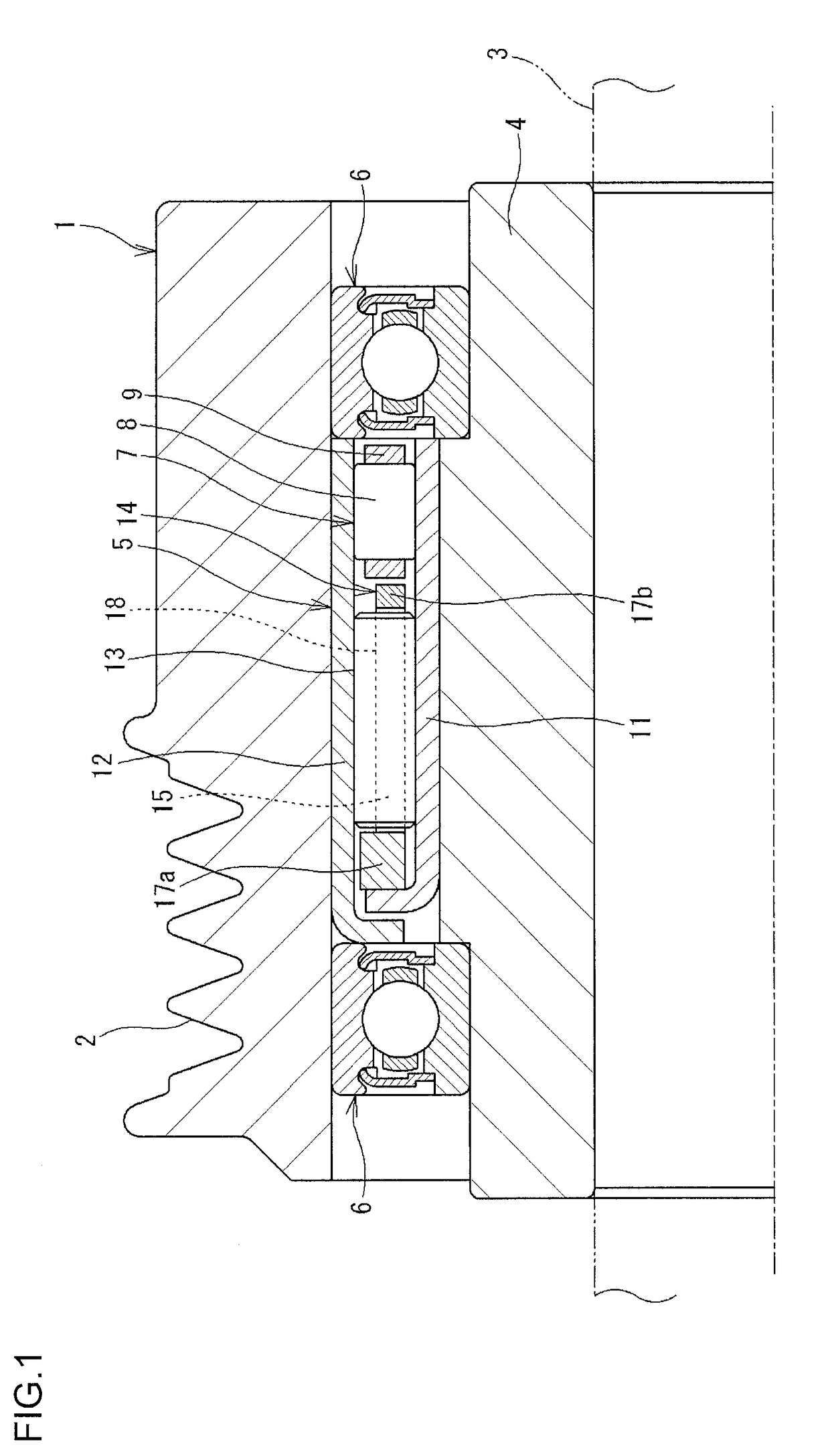
[0021]An embodiment of the invention will be described below based on the drawings. FIG. 1 is a sectional view depicting an example of a pulley apparatus including a one-way clutch. A pulley apparatus 1 depicted in FIG. 1 is used for an alternator mounted in an automobile. Although not depicted in the drawings, rotation of a crankshaft of an engine of the automobile is transmitted to the alternator via an endless belt. Thus, the pulley apparatus depicted in FIG. 1 includes a pulley portion 2 around which the endless belt is wound.

[0022]The pulley apparatus 1 includes the pulley portion 2, a sleeve 4, a one-way clutch 5, and a pair of rolling bearings 6, 6. The sleeve 4 rotates integrally with a rotating shaft 3. The one-way clutch 5 and the rolling bearings 6, 6 are provided between the pulley portion 2 and the sleeve 4. The pulley apparatus 1 is of a type having a built-in one-way clutch. The pulley portion 2 is a cylindrical member around the outer periphery of which the endless b...


PUM


Abstract

A one-way clutch includes an inner ring, an outer ring, a plurality of rollers, an annular cage that holds the rollers, and springs that bias the rollers toward a first side in a circumferential direction. The inner ring has a rib portion located on a first side in an axial direction and protruding outward in a radial direction. The cage has a pair of annular portions provided on the first side and a second side in the axial direction with respect to the rollers and a plurality of cage bars. One of the annular portions on the first side in the axial direction has an abutting contact surface that comes into abutting contact with the rib portion in the axial direction.

Description

INCORPORATION BY REFERENCE[0001]The disclosure of Japanese Patent Application No. 2015-245388 filed on Dec. 16, 2015 including the specification, drawings and abstract, is incorporated herein by reference in its entirety.BACKGROUND OF THE INVENTION[0002]1. Field of the Invention[0003]The invention relates to a one-way clutch.[0004]2. Description of the Related Art[0005]A one-way clutch is used for various types of equipment (see, for example, Japanese Patent Application Publication No. 2013-257024 (JP2013-257024 A)), by way of example, for an alternator in an automobile. As depicted in FIG. 6, a one-way clutch includes an inner ring 90, an outer ring 91, a plurality of rollers 92, an annular cage 93, and springs 94. The rollers 92 are provided between the inner ring 90 and the outer ring 91. The cage 93 holds the rollers 92. The springs 94 bias the rollers 92. A plurality of cam surfaces 95 is formed on an outer periphery of the inner ring 90. A wedge-like space 100 is formed betwee...

Claims


Application Information

Patent Timeline
Patent Type & Authority Applications(United States)
IPC IPC(8): F16D41/067
CPCF16D41/067F16D41/066F16D2041/0605
Inventor YAMAMOTO, IKUOYAMATANI, TOMOYA
Owner JTEKT CORP
Why Eureka
Try Eureka