Depalletizing Device

a technology of depalletizing device and roller, which is applied in the direction of programme control, pile separation, instruments, etc., can solve the problems of increasing the spring force and thus the pressing force of the roller on the object, and achieve the effect of reducing power very quickly and quickly adjusting power

Inactive Publication Date: 2009-01-29
CSI INDS
View PDF11 Cites 11 Cited by
  • Summary
  • Abstract
  • Description
  • Claims
  • Application Information

AI Technical Summary

Benefits of technology

[0006]As the carriage is driven with low power, the roller is applied to the object to be depalletized at a low speed. The device according to the invention is suitable for depalletizing objects of varying dimensions and weight. The power is automatically increased if this is required in order to raise the respective object, thus ensuring that the roller is applied to the object with a force which is as low as possible. The latter is advantageous in order to prevent the object from being damaged or crushed.
[0007]In one preferred embodiment, the carriage is driven by an electrically driven frequency motor or servomotor. Using these types of motors, the power can be quickly adjusted. Thus, when an object has been raised, the power can be reduced very quickly, so that the carriage does not slip, which could lead to damage to the object or to the palletized objects situated behind it.

Problems solved by technology

When the roller touches an object on the pallet, the spring is pushed in, resulting in an increase in the spring force and thus the pressing force of the roller on the object.

Method used


Image

  • Depalletizing Device
  • Depalletizing Device
  • Depalletizing Device

Examples


Embodiment Construction

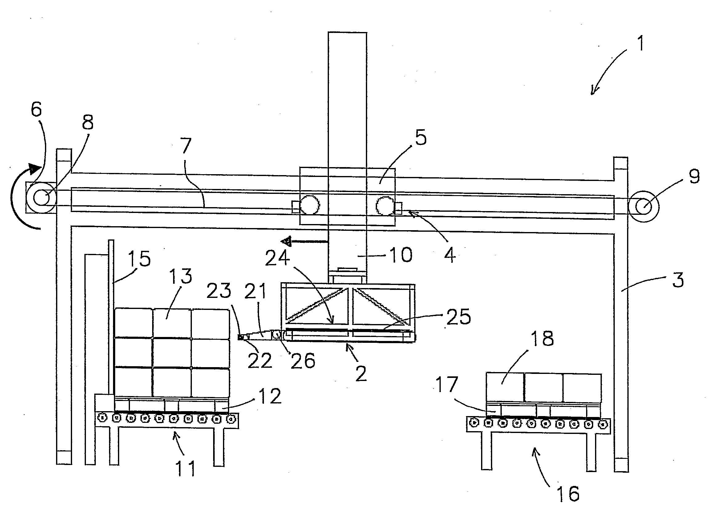
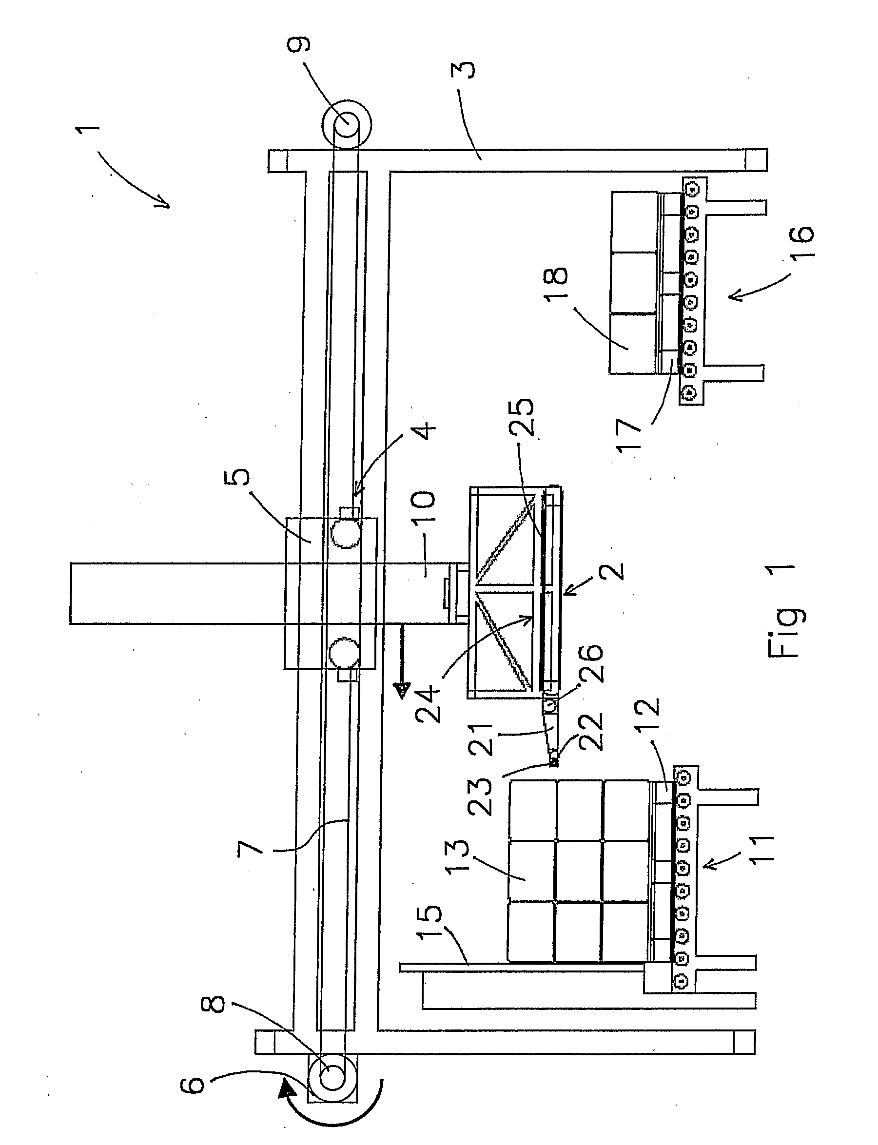
[0018]FIG. 1 shows a depalletizing device 1. The depalletizing device 1 comprises a carriage 2 and a preferably gantry-shaped stationary frame 3. The carriage 2 is coupled to a travelling crab 5 which is displaceable in a horizontal direction over a guide 4 attached to the frame 3 by means of a motor 6, arranged on the frame 3. The travelling crab 5 is coupled to the motor 6 by means of a chain 7 or another suitable transmission element. The chain 7 is guided over a chain wheel 8 driven by the motor 6 and over a freely rotatable chain wheel 9 which is located on the other side of the frame 3. A transmission, for example a gear reduction, may be arranged between the chain wheel 8 and the motor 6. The chain 7 is fixedly connected to the travelling crab 5 so that the latter is moved along the guide 4 by rotation of the chain wheel 7 of the motor 6.

[0019]The carriage 2 is vertically displaceable relative to the travelling crab 5 and thus relative to the stationary frame 3 by means of li...


PUM


Abstract

The invention relates to a depalletizing device comprising a carriage as well as a friction roller attached to the carriage, which friction roller is rotatable about a horizontal rotation axis and is coupled to a rotational drive in order to rotate. The carriage can be moved to and fro in a direction at right angles to the rotation axis of the friction roller in order to push the friction roller against a side of an object on the pallet in such a manner that the friction roller exerts an upward friction force on the object as a result of which the object is raised on that side, and in order for the friction roller to pass underneath said object after the latter has been raised. The depalletizing device comprises drive means with variable driving power in order to drive the carriage. The drive means comprise detection means. The drive means are designed such that, when the carriage moves, it is driven with a power of not more than a base value and that, when the friction roller engages on the side of the object, the driving power is increased from that power until the detection means detect that the object has been raised. The power is then immediately reduced to the power of not more than the said base value when the detection means detect that the object has been raised sufficiently high.

Description

CROSS-REFERENCES TO RELATED APPLICATIONS[0001]This application is a U.S. National Phase of PCT / NL2006 / 000041, filed Jan. 25, 2006, which claims priority to Netherlands Patent Application No. 1028344, filed Feb. 18, 2005. The contents of both of the aforementioned applications are herein incorporated by reference in their entirety.BACKGROUND OF THE INVENTION[0002]The invention relates to a depalletizing device for lifting up objects loaded onto a pallet. More in particular, the invention relates to a depalletizing device comprising a carriage as well as a friction roller attached to the carriage, which friction roller is rotatable about a horizontal rotation axis and is coupled to a rotational drive in order to rotate, the carriage being movable to and fro in a direction at right angles to the rotation axis of the friction roller in order to push the friction roller against a side of an object on the pallet in such a manner that the friction roller exerts an upward friction force on ...

Claims


Application Information

Patent Timeline
Patent Type & Authority Applications(United States)
IPC IPC(8): B65G59/02
CPCB65G59/023B65G59/02
Inventor VAN DE KLUNDERT, MARK
Owner CSI INDS
Why Eureka
Try Eureka