Remaining electrical charge/remaining capacity estimating method, battery state sensor and battery power source system

a technology of remaining electrical charge/remaining capacity and estimating method, which is applied in the direction of resistance/reactance/impedence, instruments, and variable measurement arrangements, etc., can solve the problem of difficult to approximate the open circuit voltage of the secondary battery with time characteristic with high accuracy, and the convergence value of the open circuit voltage might show a large error, etc. problem, to achieve the effect of short time and high calculation accuracy

Active Publication Date: 2009-01-29
FURUKAWA ELECTRIC CO LTD
View PDF4 Cites 22 Cited by
  • Summary
  • Abstract
  • Description
  • Claims
  • Application Information

AI Technical Summary

Benefits of technology

[0020]As described above, according to the present invention, a stable open circuit voltage estimated value after a lapse of desired time is obtained by the step of using an approximate function including a plurality of exponential function terms of time and a plurality of coefficients, stopping charge and discharge operation for a predetermined time, measuring the battery voltage over time in the meantime, determining the coefficients based on the obtained battery voltage-time relation, and the step of determining at least one power coefficient of inferior logarithm in each of the exponential function terms based on temperature by expressing the coefficient as a previously obtained function of temperature.
[0021]Besides, a stable open circuit voltage estimated value after a l...

Problems solved by technology

However, the open circuit voltage of the secondary battery has to be obtained while charge or discharge is not performed, and it takes long time until the open circuit voltage becomes stable after charge or discharge is finished.
However, it is difficult to approximate the open circuit voltage of the secondary battery with time characteristic with high accuracy, and the obtained...

Method used


Image

  • Remaining electrical charge/remaining capacity estimating method, battery state sensor and battery power source system
  • Remaining electrical charge/remaining capacity estimating method, battery state sensor and battery power source system
  • Remaining electrical charge/remaining capacity estimating method, battery state sensor and battery power source system

Examples


first embodiment

[0067]A feature of the present invention is, when estimating a stable open circuit voltage by fitting with the equation (5), first obtaining at least one of relaxation time coefficients in the equation (5), that is, coefficients A5, A6, A7, A8, antilog of inferior logarithm as the temperature function f1(t), f2(t), f3(t), f4(t) and then performing fitting calculation with a relaxation time coefficient at each temperature being a fixed value.

[0068]In this embodiment, it is assumed that the coefficients A5, A6, A7 and A8 are expressed by temperature functions. Then, the exponential decay function is expressed by the equation (6) and t in the function f1(t), f2(t), f3(t), f4(t) denotes temperature.

F(T)=A1exp{f,(t)T}+A2exp{f2(t)T}+A3exp{f3(t)T}+A4exp{f4(t)T}+A9  (6)

[0069]If f1(t), f2(t), f3(t) and f4(t) in the equation (6) are obtained in advance by experiment and a temperature at a certain point is obtained, f1(t), f2(t), f3(t) and f4(t) can be treated as fixed values. The exponential ...

second embodiment

[0080]the present invention has its second feature in, when estimating a stable open circuit voltage by fitting with the function expressed by the equation (5), first calculating a correlation between relaxation time coefficients in the equation (5), that is, antilogs of inferior logarithm and then, performing fitting calculation, for example, with at least one of the coefficients A6, A7 and A8 used as functions g1(A5), g2(A5) and g3(A5) of the coefficient A5.

[0081]In this embodiment, all of the A6, A7 and A8 are expressed by the functions with the coefficient A5, that is, g1(A5), g2(A5), g3(A5), and for easy explanation, it is assumed that the relations A6=αA5, A7=βA5, A8=γA5 are satisfied for example. In this case, the exponential decay function is given by the equation (12) where α, β, γ are constants obtained in advance by experiment or the like.

F(T)=A1exp(A5T)+A2exp(αA5T)+A3exp(βA5T)+A4exp(γA5T)+A6  (12)

[0082]Next, the above-described exponential decay function F(T) is adopted ...

third embodiment

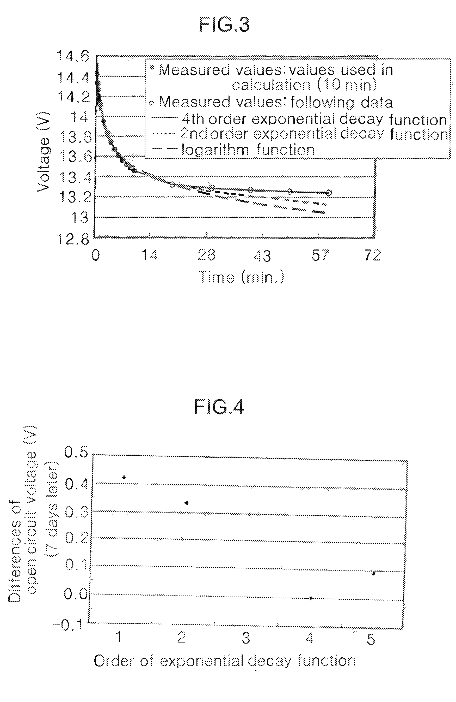
[0088]Next description is made about the present invention. As described above, in the vehicle battery system of the embodiments, the open circuit voltage is obtained by approximation with 4th order or more exponential decay function for keeping high accuracy in iterating calculations. However, even if the 4th order or more exponential decay function is set, a lower order exponential decay function can be used to perform iterating calculation depending on conditions of the vehicle battery system. The description below is made about, as a modification of the embodiment, a specific calculation method of using substantially-lower-order exponential decay function to realize reduction in calculation load.

[0089]In the third embodiment, utilizing different influence between terms of the exponential decay function depending on the timings to obtain the plural sample voltages (hereinafter referred to as “voltage measurement timing”) a given time along the time axis after charge and discharge...


PUM


Abstract

The present invention provides a battery remaining electrical charge/remaining capacity estimating method which makes it possible to obtain a convergence value of a battery open circuit voltage with high accuracy and in a short time.
The method includes a voltage estimating step of obtaining a stable open circuit voltage estimated value after a lapse of desired time, the step including: a step of using an approximate function including a plurality of exponential function terms of time and a plurality of coefficients, stopping charge or discharge operation for a predetermined time, measuring a battery voltage over time during the time and using an obtained relation between the battery voltage and the time as a basis to determine the coefficients; and a step of determining at least one power coefficient of inferior logarithm of the exponential function terms based on temperature by expressing the coefficient as a previously obtained function of temperature.

Description

TECHNICAL FIELD[0001]The present invention relates to a method for estimating a remaining electrical charge / remaining capacity of a battery for supplying power to a load, a sensor for detecting a state of the battery and a battery power source system having such a sensor.BACKGROUND ART[0002]Conventionally, there are demands for accurately obtaining a remaining electrical charge of a secondary battery for backup or power source of various devices or a secondary battery such as a lead battery mounted on a vehicle. Generally, in the secondary battery, as there is a correlation between a remaining electrical charge and an open circuit voltage, the remaining electrical charge can be estimated by obtaining the open circuit voltage. However, the open circuit voltage of the secondary battery has to be obtained while charge or discharge is not performed, and it takes long time until the open circuit voltage becomes stable after charge or discharge is finished. Therefore, there has been propo...

Claims


Application Information

Patent Timeline
IPC IPC(8): G01R31/36
CPCG01R31/3651G01R31/362G01R31/367G01R31/3835
Inventor IWANE, NORIYASUWATANABE, YUICHISATO, TOSHIYUKIKIMURA, ATSUSHIIWAHANA, FUMIKAZU
Owner FURUKAWA ELECTRIC CO LTD
Why Eureka
Try Eureka