
Blind signature method and its system

a blind signature and signature technology, applied in the field of blind signature methods and their systems, can solve the problem that the signature function cannot always be used for blind signatures

Inactive Publication Date: 2009-01-29
NEC CORP
View PDF3 Cites 12 Cited by
  • Summary
  • Abstract
  • Description
  • Claims
  • Application Information

AI Technical Summary

Benefits of technology

[0010]In the invention as configured above, a plurality of message candidates are generated and coded to the first quantum state by quantum coding means at the signature requestor terminal device. The first quantum state is the superposed state in which the plurality of message candidates are coded. The signature requestor terminal device sends the first quantum state to the signer terminal device, using quantum communication means. At this time, if the first quantum state is measured to specify the message candidate at the signature requestor terminal device, the quantum state superposition is abandoned, causing the first quantum state to transit to another quantum state. In this way, since the plurality of message candidates are coded to one quantum state, the message cannot be specified without any trace remaining at the signer terminal device. On the other hand, at the signer terminal device, the first quantum state is inputted into the quantum calculation means, which calculates the signature function, whereby it is possible to issue the signature for the plurality of message candidates without specifying the message, and to generate one second quantum state in

Problems solved by technology

In this way, the signature function usable for the blind signature method is required to have a special mathematical property such as a multiplicative property, and has a problem in which any signature function cannot always be used for the blind signature.

Method used


Image

  • Blind signature method and its system
  • Blind signature method and its system
  • Blind signature method and its system

Examples


first exemplary embodiment

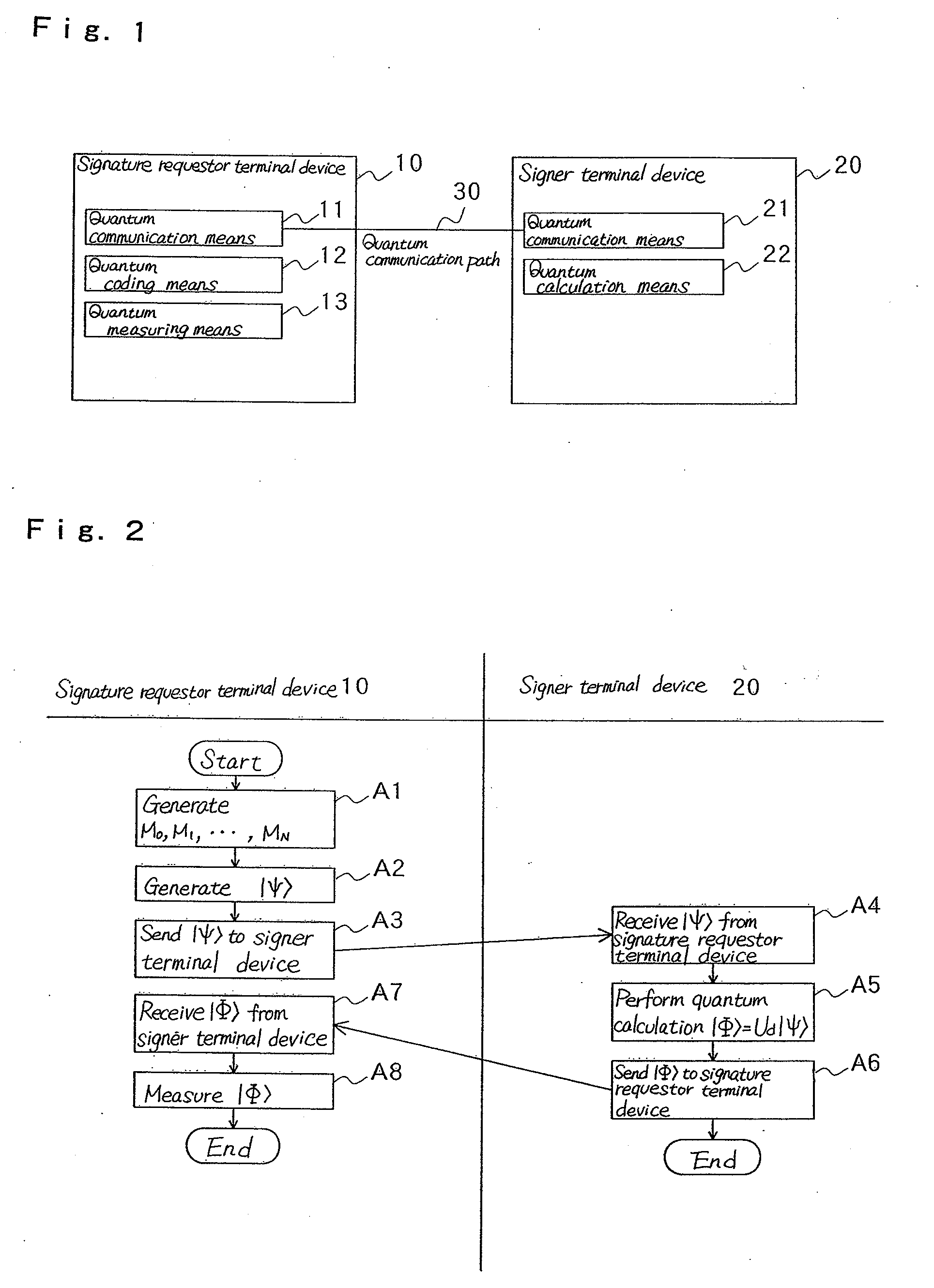
[0016]FIG. 1 is a view showing a blind signature system according to a first exemplary embodiment of the present invention.

[0017]In this exemplary embodiment, signature requestor terminal device 10 that requests a signature on a message, and signer terminal device 20 that issues the signature to the message provided by signature requester terminal device 10 that uses a signature function are connected via quantum communication path 30, in which signature requestor terminal device 10 comprises first quantum communication means 11, quantum coding means 12 and quantum measuring means 13, and signer terminal device 20 comprises second quantum communication means 21 and quantum calculation means 22, as shown in FIG. 1.

[0018]Quantum coding means 12 codes a plurality of message candidates to one first quantum state.

[0019]Quantum communication means 11 sends the first quantum state via quantum communication path 30 to signer terminal device 20.

[0020]Quantum measuring means 13 measures a sec...

second exemplary embodiment

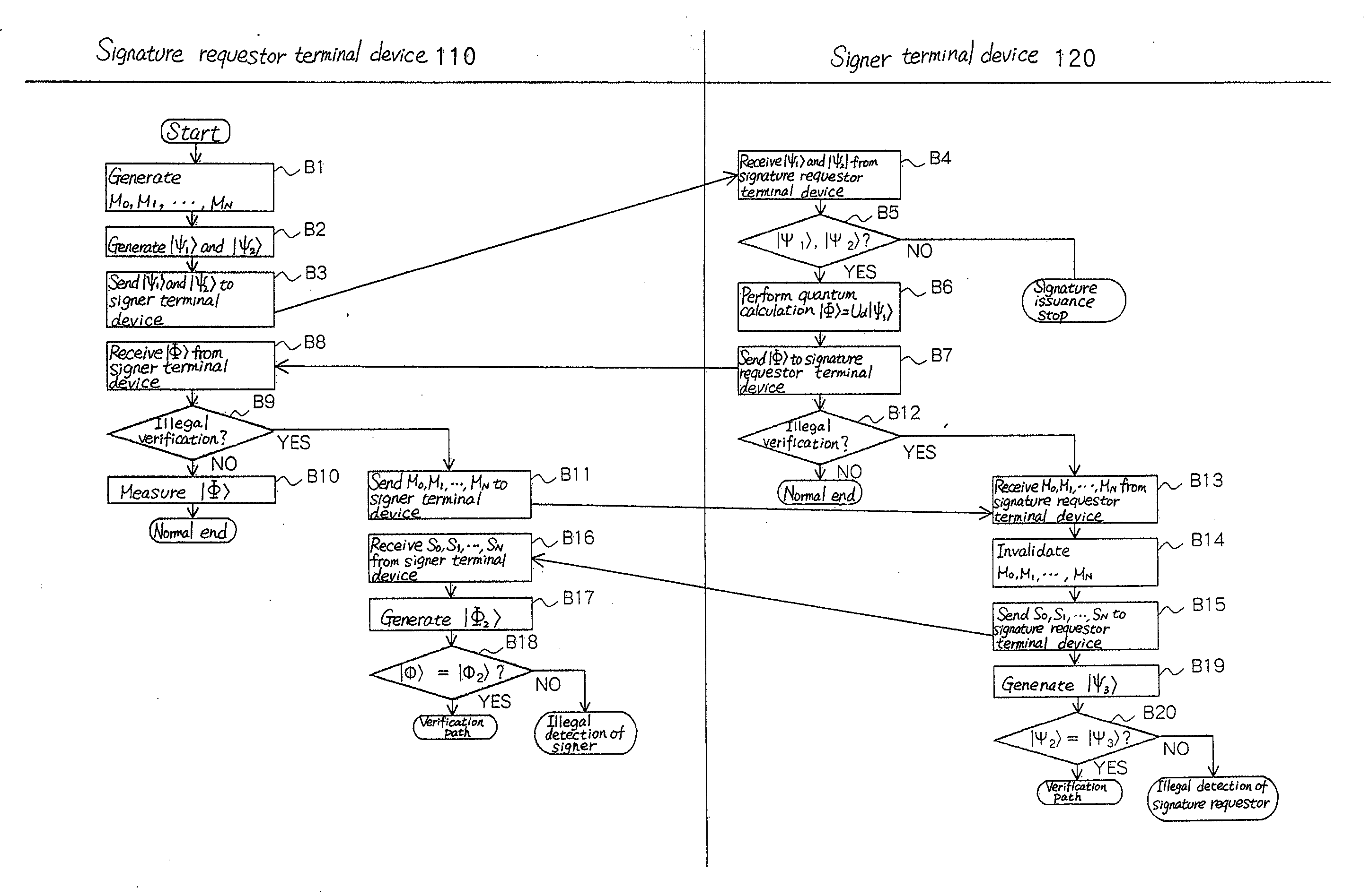
[0033]A process for detecting illegality of the signer or signature requestor anywhere in the processing flow may be added to the first exemplary embodiment. One example will be described below.

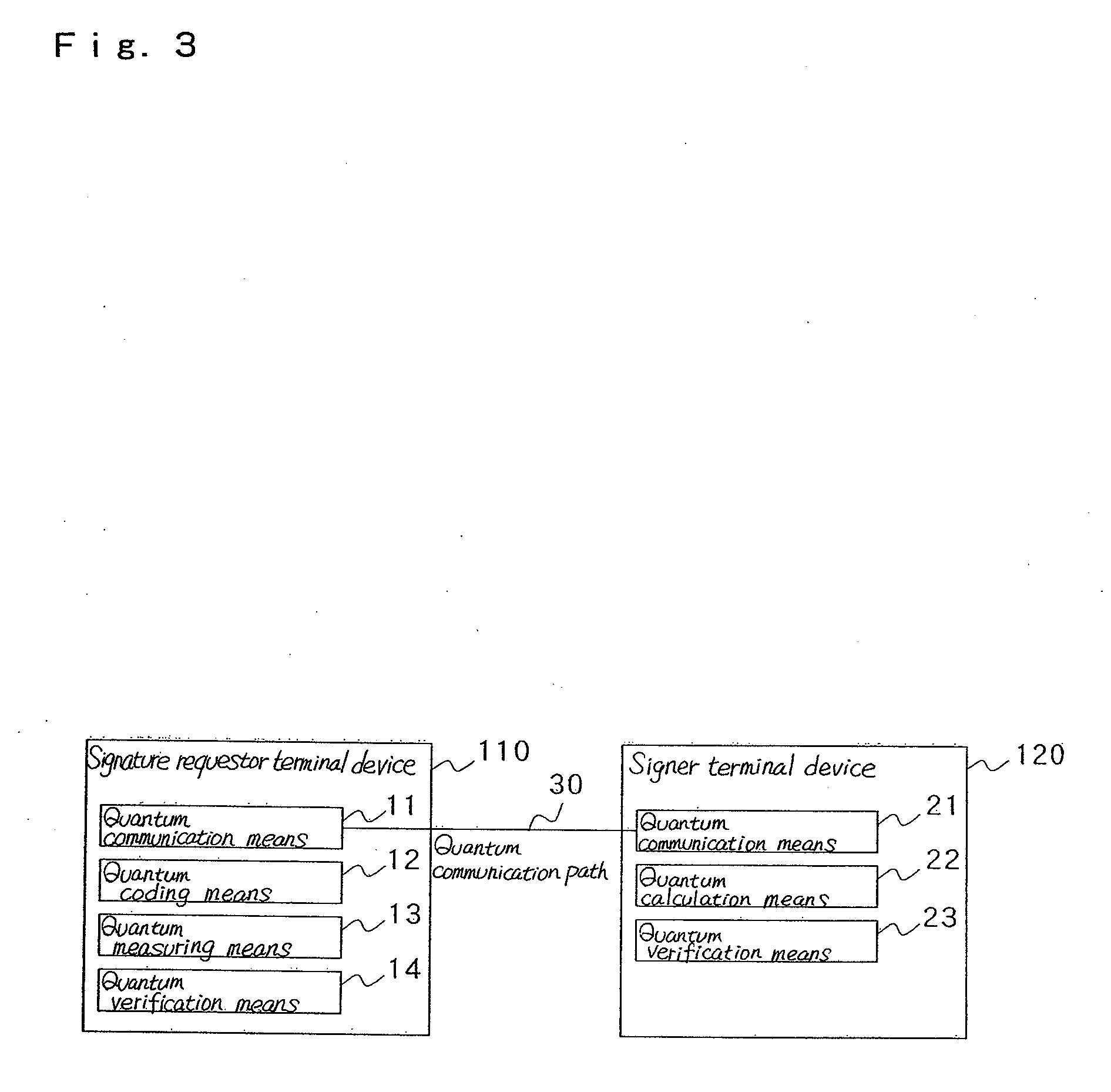
[0034]FIG. 3 is a view showing a blind signature system according to a second exemplary embodiment of the invention.

[0035]In this exemplary embodiment, unlike the first exemplary embodiment, signature requestor terminal device 110 is provided with first quantum verification means 14 and signer terminal device 120 is provided with second quantum verification means 23, as shown in FIG. 3.

[0036]Signature requestor terminal device 110 sends a plurality of message candidates via the ordinary communication line to signer terminal device 120.

[0037]Quantum coding means 12 at signature requestor terminal device 110 generates a third quantum state in which the plurality of message candidates and a plurality of signatures sent from signer terminal device 120 are coded.

[0038]Quantum verification means 14...


PUM


Abstract

Signature requestor terminal device (10) codes a plurality of messages to a quantum state and transmits it to signer terminal device (20). Signer terminal device (20) issues a blind signature for the plurality of the messages coded to the quantum state, codes the messages and the signature to a quantum state and sends them back to signature requestor terminal device (10).

Description

TECHNICAL FIELD[0001]The present invention relates to a blind signature method and its system for allowing a signer to issue a blind digital signature, in which the contents of a message are disguised, and which is to be affixed to electronic information.BACKGROUND ART[0002]A blind signature is a technique for allowing the signer to issue a signature in which the contents of a message are disguised. A method based on RSA signature was described in a document by D. Chaum, “Security without Identification: Transaction Systems to Make Big Brother Obsolete”, Communication of the ACM, Vol. 28, No. 10, pp. 1030-1044 (1985) and in U.S. Pat. No. 4,759,063. The method will be outlined as follows:[0003]Assume that a secret key of the signer is d and that a public key is (e,n), where d, e and n are integers that are chosen to satisfy ted=r mod n for any integer t. Also, assume that h is an appropriate hash function and fd is a signature function fd(x)=xd mod n in the RSA signature.[0004]First ...

Claims


Application Information

Patent Timeline
IPC IPC(8): H04L9/00
CPCH04L9/3257H04L9/0852
Inventor ISHIZAKA, SATOSHITOMITA, AKIHISA
Owner NEC CORP
Learn More