Automated Transmission Control Apparatus, Power Unit Provided With Automatic Transmission Control Apparatus, and Straddle-Type Vehicle
a technology of automatic transmission and control apparatus, which is applied in the direction of cycle, transportation and packaging, gearing, etc., can solve the problems of neither suppressing nor employing the control apparatus, and achieve the effect of suppressing the overload applied and shortening the time from starting
- Summary
- Abstract
- Description
- Claims
- Application Information
AI Technical Summary
Benefits of technology
Problems solved by technology
Method used
Image
Examples
modified embodiment 1
[0124]In the present embodiment, mechanical fuse 88 is constituted by power transmission portion 82f transmitting power from first rod structure portion 82A to second rod structure portion 82B. However, mechanical fuse 88 is not limited to this structure. For example, as shown in FIGS. 13 and 14, mechanical fuse 88 may be constituted by a power transmission portion 82h transmitting power from third shaft 81c constructing the drive (output) shaft of speed reducing mechanism 81 to operation lever 84.
[0125]Specifically, power transmission portion 82h is constituted by a plate-like body having two thin portions 82x formed between three thick portions 82y. Power transmission portion 82h is inserted to a notch portion 81z formed in the end portion of third shaft 81c. Accordingly, power transmission portion 82h is attached to third shift 81c so as to be relatively non-rotatable.
[0126]An insertion hole 84b to which third shaft 81c is inserted is formed in operation lever 84. A concave porti...
modified embodiment 2
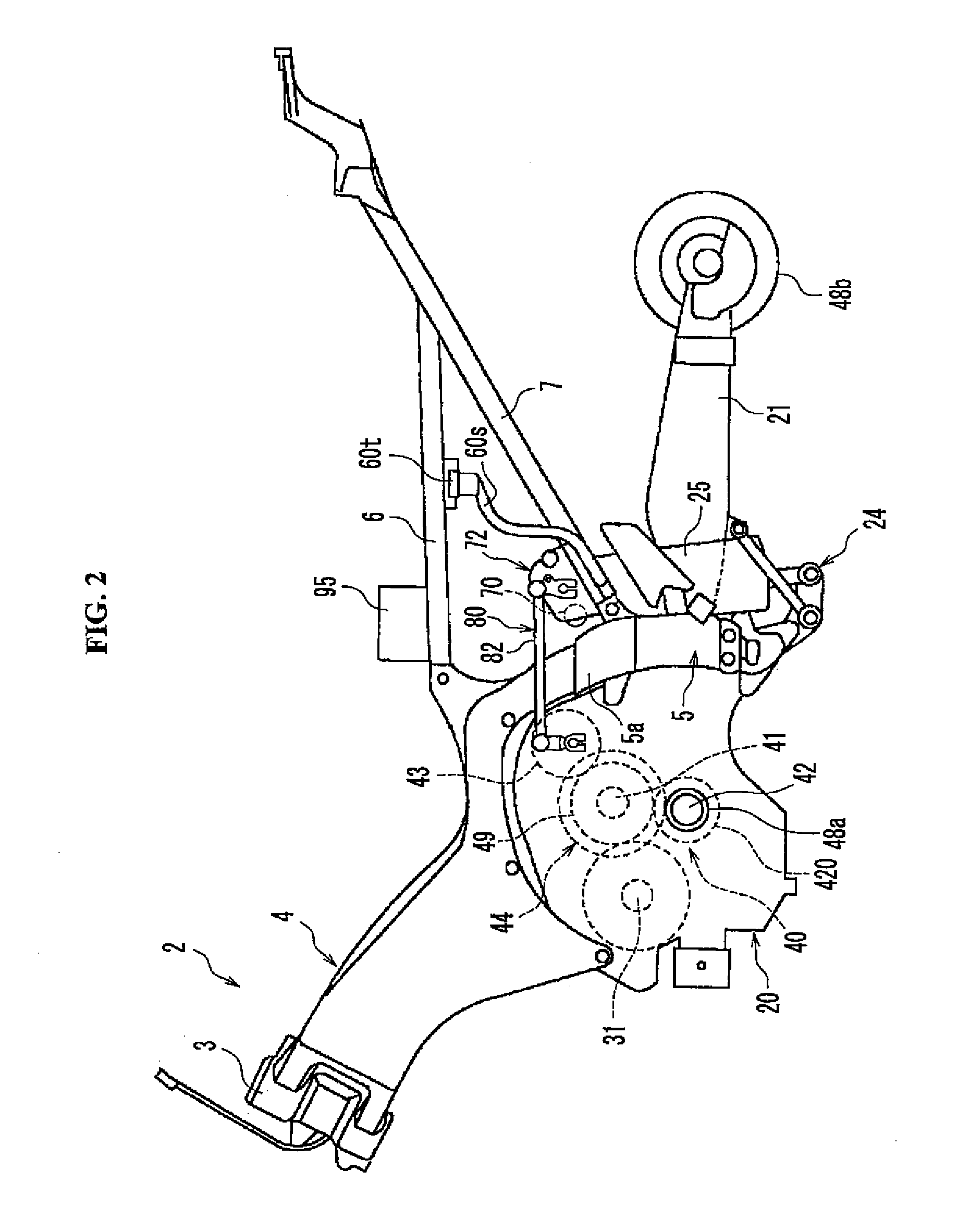
[0131]As shown in FIG. 3, shift power transmission mechanism 80 is provided with speed reducing mechanism 81 reducing the rotational speed of shift motor 70, operation lever 84, shift rod 82, operation lever 85, and shift link mechanism 83. However, shift power transmission mechanism 80 is not limited to this structure. As shown in FIG. 15, shift power transmission mechanism 80 may be constituted by speed reducing mechanism 81, shift link mechanism 83, and a coupling member 90 connecting speed reducing mechanism 81 and shift link mechanism 83. Coupling member 90 may be structured, for example, as shown in FIG. 16, by an element which coaxially couples third shaft 81c of speed reducing mechanism 81 and shift operation shaft 83a of shift link mechanism 83 so as to be relatively non-rotatable.
[0132]As shown in FIG. 16, an engagement hole 91 extending from one side toward the other side is formed in coupling member 90 in accordance with modified embodiment 2. Engagement hole 91 is forme...
PUM
 Abstract
Description
Claims
Application Information
 - R&D
- Intellectual Property
- Life Sciences
- Materials
- Tech Scout
- Unparalleled Data Quality
- Higher Quality Content
- 60% Fewer Hallucinations
Browse by: Latest US Patents, China's latest patents, Technical Efficacy Thesaurus, Application Domain, Technology Topic, Popular Technical Reports.
© 2025 PatSnap. All rights reserved.Legal|Privacy policy|Modern Slavery Act Transparency Statement|Sitemap|About US| Contact US: help@patsnap.com


