Waterproof case for electronic device

a technology for electronic devices and waterproof cases, applied in the direction of instruments, packaging goods, transportation and packaging, etc., can solve the problems of poor durability of the panel, difficult to secure the durability of the waterproof case, and the technique is not so useful, so as to improve the durability of the operating member and secure the operation of the touch panel display.

Inactive Publication Date: 2009-02-05
SONY CORP
View PDF1 Cites 124 Cited by
  • Summary
  • Abstract
  • Description
  • Claims
  • Application Information

AI Technical Summary

Benefits of technology

[0012]According to one embodiment of the present invention, there is provided a waterproof case for an electronic device, the case having an improved durability while securing the operability of the touch panel display.
[0014]According to an embodiment of the present invention, the operating member for operating the touch panel display includes the operating portion, the arm, and the contact portion. Multiple operating portions and a boss portion supporting the portions are able to be disposed outside the profile of the touch panel display. The operability of the touch panel display is secured, and the durability of the operating members is improved.

Problems solved by technology

Disadvantageously, this technique is not so useful.
Disadvantageously, the input panel has poor durability, and thus it is difficult to secure the durability of the waterproof case.

Method used


Image

  • Waterproof case for electronic device
  • Waterproof case for electronic device
  • Waterproof case for electronic device

Examples


first embodiment

[0033]An embodiment in which an electronic device accommodated in a waterproof case for an electronic device (hereinafter called a waterproof case) is a digital still camera is explained below.

[0034]First, the digital still camera (electronic device) to be accommodated in a waterproof case 30 (FIG. 3) is explained.

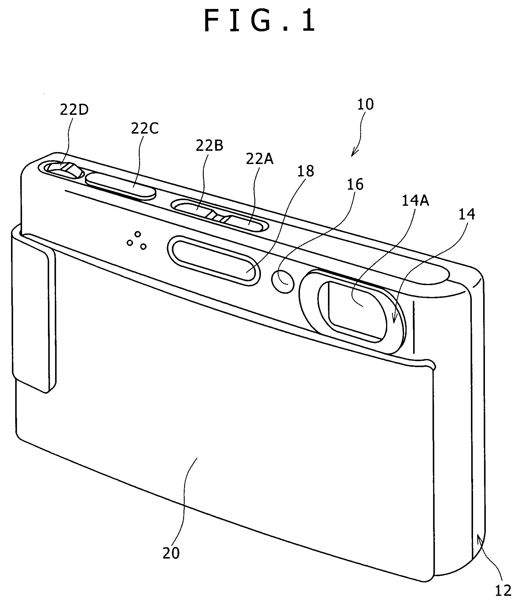
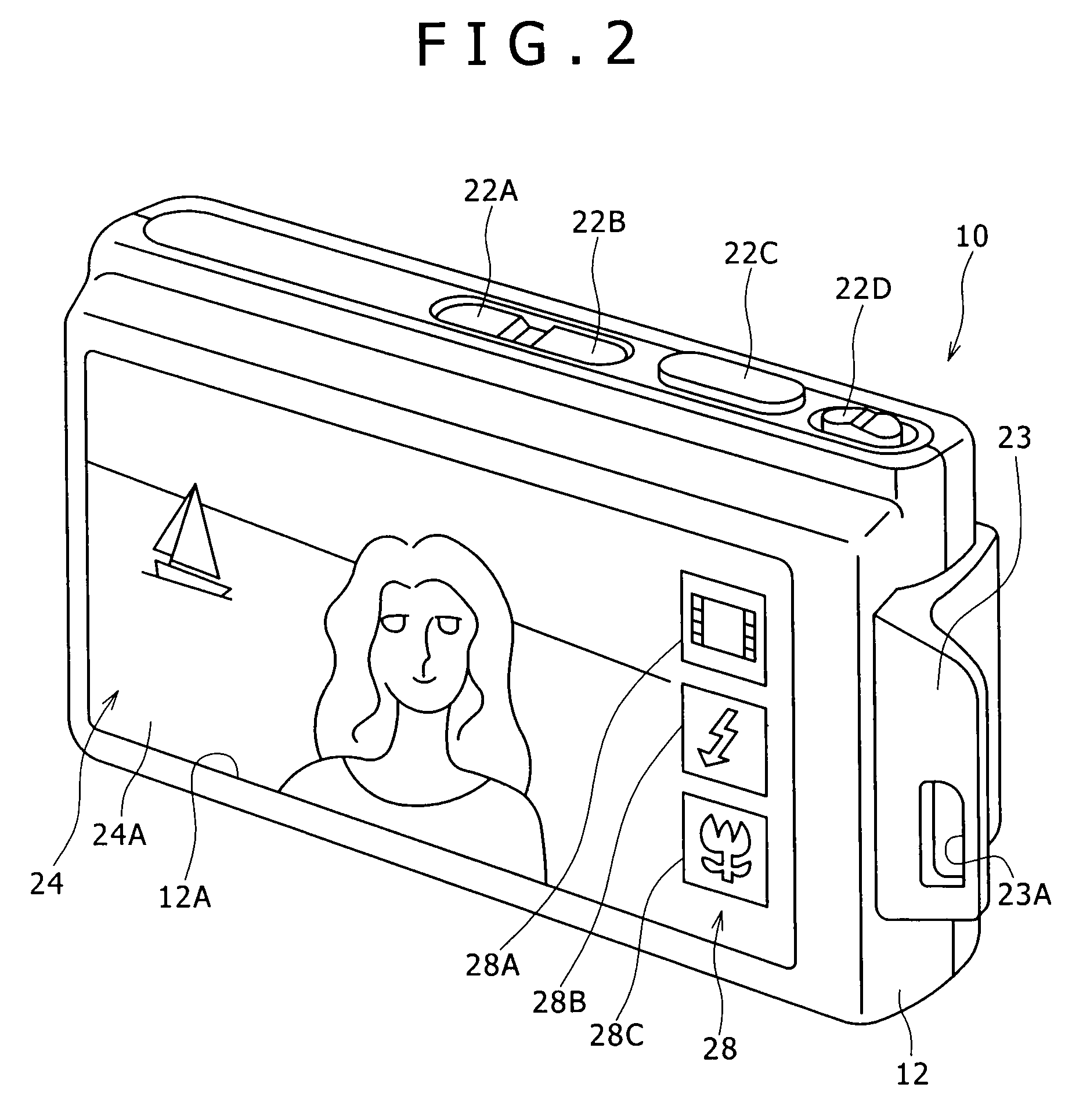
[0035]FIG. 1 is a perspective view of a digital still camera 10 viewed from the front. FIG. 2 is a perspective view of the digital still camera 10 viewed from the back.

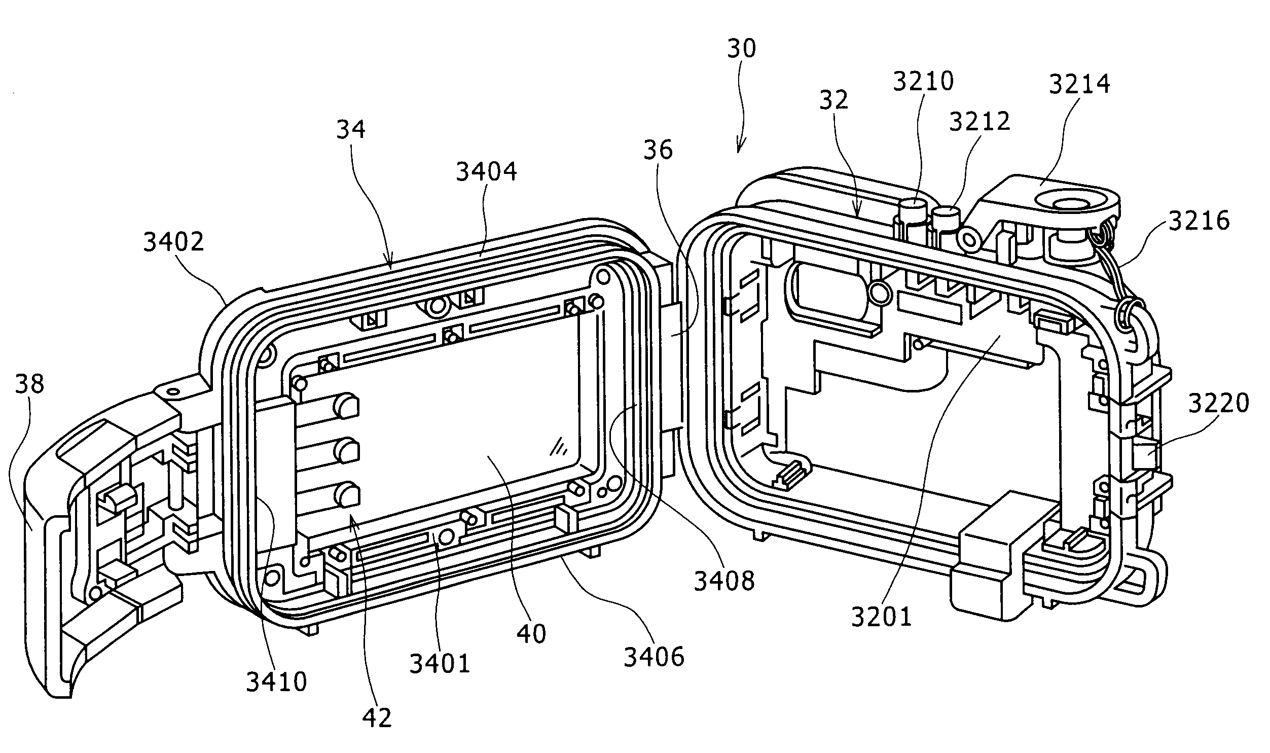
[0036]According to this embodiment, the digital still camera 10 to be accommodated in the waterproof case 30 has a body 12 forming the exterior. The right and left in this specification are the directions when the waterproof case 30 and the digital still camera are seen from the back, the front in this specification is the direction of the subject, and the back in this specification is the direction of the imaging element.

[0037]As shown in FIG. 1, a lens barrel 14 which accommodates and holds an imaging opti...

second embodiment

[0104]A second embodiment is disclosed below.

[0105]The second embodiment differs from the first embodiment in the structure of the pressure regulating portion.

[0106]FIG. 14 is a perspective view showing the structure of the operating member 42 in the second embodiment. FIG. 15 is a sectional view showing the non-operating state of the operating member 42 in the second embodiment. FIG. 16 is a sectional view showing the operating state of the operating member 42. The same portions in the second embodiment as those in the first embodiment are given the same reference numerals as those of the portions in the first embodiment, and not explained.

[0107]That is, as shown in FIGS. 14 and 15, the operating member 42 includes the operating portion 44, the arm 46, the contact portion 48, and a pressure regulating portion 50A. The push button 44A is disposed in the concave 41A via the spring 44C for the operating portion, and the shaft 44B penetrates the back wall 3402 via a sealant 52.

[0108]Th...

third embodiment

[0114]A third embodiment differs from the first and second embodiments in the shape of the arm 46.

[0115]FIG. 17A is a perspective view of the arm 46 and contact portion 48 in the third embodiment. FIG. 17B shows a view from an arrow B.

[0116]According to the third embodiment, as shown in FIGS. 17A and 17B, the arm 46 and contact portion 48 are formed integrally by use of a single steel wire rod.

[0117]The both longitudinal ends of the wire rod are formed as a coil portion 70 wound into a coiled shape. The coil portion 70 is connected to the end of the shaft 44B (FIG. 8), the end being disposed inwardly from the back wall 3402 (FIG. 8).

[0118]The arm 46 extends linearly from the portion of the operating portion 44 with the portions of the wire rod opposing to each other.

[0119]The contact portion 48 is formed by bending the tops of the portions of the wire rod and connecting the tops each other, the portions opposing to each other and linearly extending, to cause the top be convex toward...


PUM


Abstract

A waterproof case is provided for an electronic device having a touch panel display. The waterproof case includes an operating member for operating the touch panel display. The operating member includes: an operating portion which penetrates from the outer surface to inner surface of a wall forming the waterproof case in a watertight manner and which is disposed to be able to be pushed from the outer surface of the wall; an arm extending from a portion of the operating member, the portion being disposed inwardly from the wall, in the direction transverse to the direction in which the operating portion is pushed; and a contact portion which is provided to an end of the arm and is contacted with the touch panel display in response to the push of the operating portion.

Description

CROSS REFERENCES TO RELATED APPLICATIONS[0001]The present invention contains subject matter related to Japanese Patent Application JP 2007-203100 filed in the Japanese Patent Office on Aug. 3, 2007, the entire contents of which being incorporated herein by reference.BACKGROUND OF THE INVENTION[0002]1. Field of the Invention[0003]The present invention relates to a waterproof case for an electronic device, more particularly, a waterproof case for a compact electronic device such as a digital still camera.[0004]2. Description of the Related Art[0005]Multiple operating members are often provided to a waterproof case for an electronic device to operate operation switches of an electronic device accommodated in the case. Such operating members include push buttons provided in the external surface of the waterproof case, and contact portions which are provided to the inner surface of the waterproof case and which push the operation switches in response to a push of the push buttons. The el...

Claims


Application Information

Patent Timeline
Patent Type & Authority Applications(United States)
IPC IPC(8): B65D85/38G03B17/08
CPCG03B17/08
Inventor ZENZAI, MITSURU
Owner SONY CORP
Why Eureka
Try Eureka