
Power-circuit breaking device

a power-circuit and circuit-breaking technology, applied in the direction of air-breaking switch details, substation/switching arrangement details, switches with unconnected briding contacts, etc., can solve the problems of large number of process steps and large number of components, and achieve the effect of simple structure, reduced number of components, and easy mounting

Active Publication Date: 2009-02-05
YAZAKI CORP
View PDF18 Cites 33 Cited by
  • Summary
  • Abstract
  • Description
  • Claims
  • Application Information

AI Technical Summary

Benefits of technology

[0015]According to the power-circuit breaking device of the present invention, the housing includes the lock member for locking the fuse, so that the fuse can be mounted easily on the housing by press-fitting the fuse into the housing. It is possible to provide a power-circuit breaking device which has a smaller number of components and has a simpler structure. Completion of fixing the fuse on the housing can be recognized by seeing locking of the lock member and the fuse. Furthermore, since the cover has a limiter functioning to prohibit the lock member from displacing to unlock the locked fuse when the cover is mounted on the housing, it can be prevented that the fuse falls out of the housing. Thus, with a smaller number of components and a simpler structure, the fuse can be securely fixed on the housing.
[0016]According to the power-circuit breaking device of the present invention, completion of locking the fuse on the housing can be recognized by normal mounting of the lock member and the fuse.
[0017]According to the power-circuit breaking device of the present invention, the lock member is engaged into the cutout arranged at the bent corner of each terminal portion. Therefore, the lock member holds the terminal portion in a direction perpendicular to a cross section of the terminal portion so that the fuse can be held in the housing without deformation of the terminal portion.
[0018]According to the power-circuit breaking device of the present invention, the housing and the cover further include the cover lock set locking to each other. Thus, an internal structure of the housing can be simplified so that a molding die for the housing can be simplified.

Problems solved by technology

Therefore, the number of components is large and the number of process steps is large.

Method used


Image

  • Power-circuit breaking device
  • Power-circuit breaking device
  • Power-circuit breaking device

Examples


Embodiment Construction

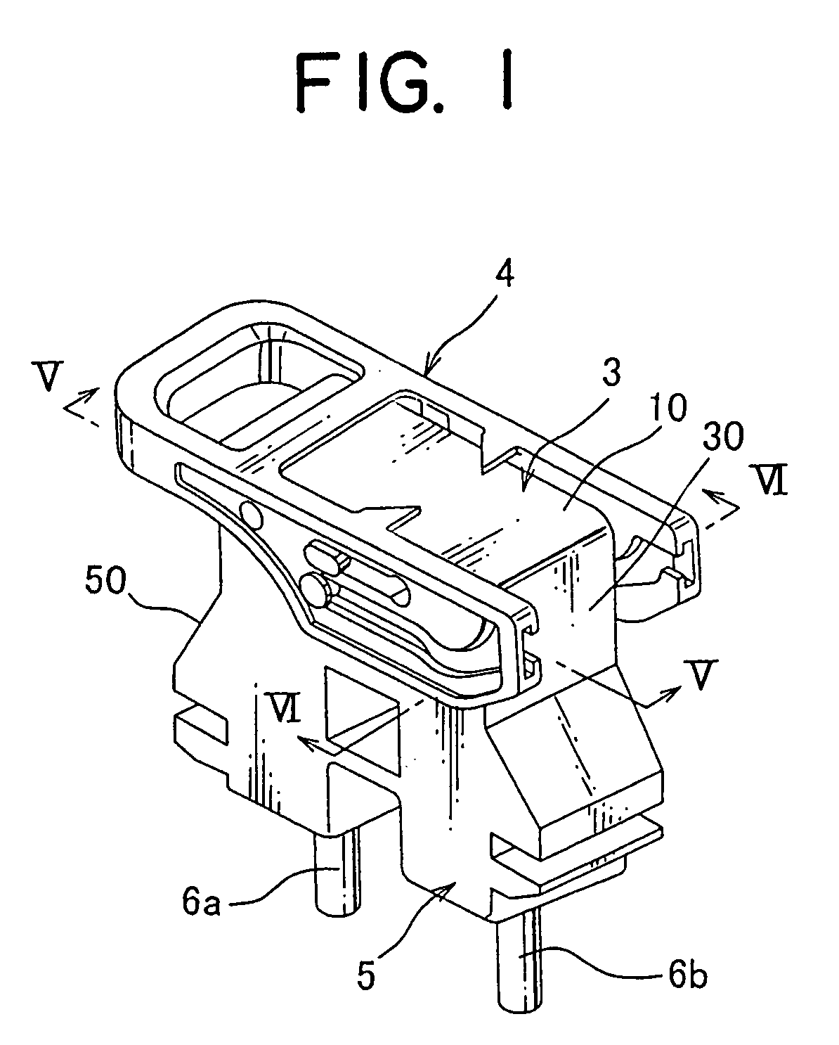
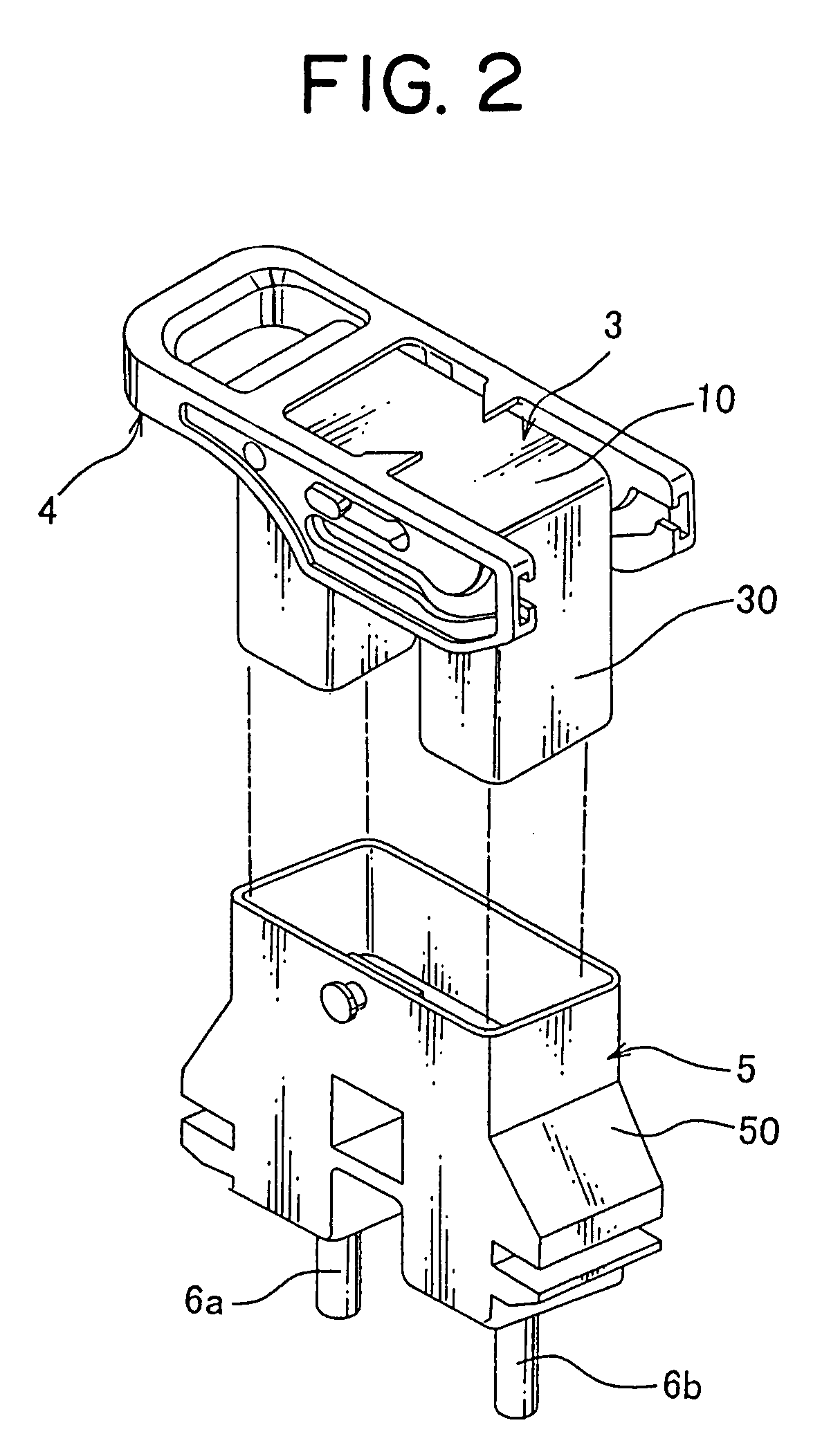
[0028]A power-circuit breaking device (so-called service plug) of one embodiment according to the present invention will be described with reference to FIGS. 1-6. The power-circuit breaking device 1 of the embodiment is applied into a power circuit for supplying electric power from a battery in an electric vehicle to a load apparatus so as to open and close the power circuit according to requirements.

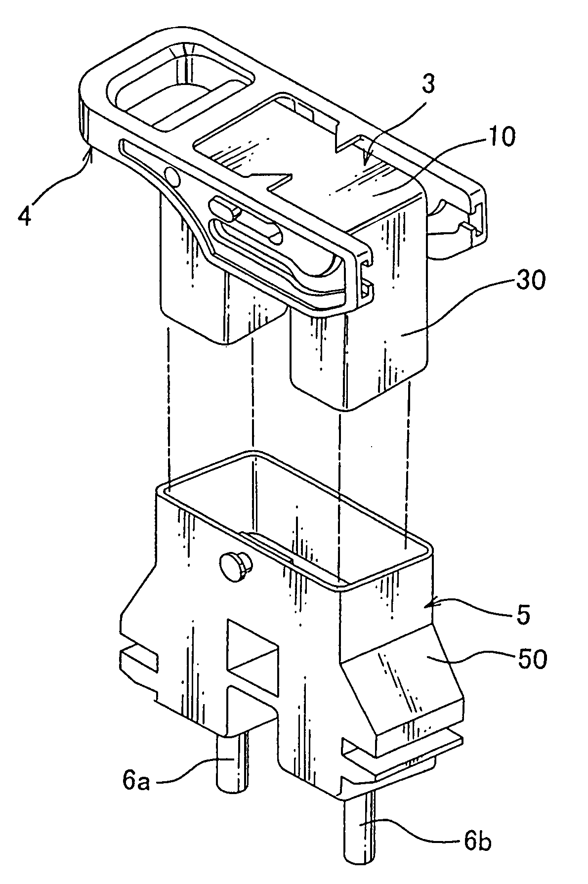
[0029]The power-circuit breaking device 1, as shown in FIGS. 1 and 2, includes a first connector housing 5, a plastic lever 4 and a second connector housing 3 connecting / disconnecting with the first connector housing 5 by operation of the lever 4.

[0030]The second connector housing 3 includes a plastic housing 30, a fuse 20 including a later-described fuse body 21 and a later-described pair of terminals 22 and press-fitted into a receiving section 7 of the housing 30, and a plastic cover 10 covering an entry opening of the receiving section 7.

[0031]The first connector housing 5, as shown...


PUM


Abstract

For providing a power-circuit breaking device, which can easily mount a fuse and has a small number of component and a simple structure, the power-circuit breaking device includes a first connector housing having a pair of circuit terminals connected with a power circuit, and a second connector housing closing the power circuit by fitting with the first connector housing. The second connector housing includes a fuse having a pair of terminals to be connected with the pair of circuit terminals, a housing having a lock arm engaged with a cutout provided at the terminal and a cover an entry opening of a receiving section of the housing. The cover includes a limiter limiting the lock arm to move to disengaging the terminal.

Description

[0001]The priority application Number Japan Patent Application 2007-199441 upon which this patent application is based is hereby incorporated by reference.BACKGROUND OF THE INVENTION[0002]1. Field of the Invention[0003]This invention relates to a power-circuit breaking device (service plug) for breaking a current flow by opening a power circuit.[0004]2. Description of the Related Art[0005]Since capacity of a power source such as a battery in an electric vehicle is larger than that in a normal vehicle with a gasoline engine, it is required for safety in working to open the power circuit by using a power-circuit breaking device (service plug) when maintaining an electric system. Such power-circuit breaking device by prior art is generally presented by a power-circuit breaking device 101 shown in FIGS. 7, 8 (Refer Patent Document 1: Japan Patent Published Application No. H10-83753).[0006]The power-circuit breaking device 101, as shown in FIG. 7, includes a first connector housing 102 h...

Claims


Application Information

Patent Timeline
IPC IPC(8): H01H85/02H01H9/10H01H27/00H01H85/20H01H31/12H01H31/24H01H85/045H01H85/147H01H85/22H01H85/56
CPCH01H85/547H01H85/2045
Inventor DENO, MASAHIROCHIKAMATSU, YASUKAZU
Owner YAZAKI CORP
Learn More