

Image forming apparatus
a technology of forming apparatus and forming tube, which is applied in the direction of digital output to print units, instruments, digital transmission, etc., can solve the problems of increasing the thickness of difficult to arrange the bundle of the harness in a desired place, and difficult to arrange the thick bundle of the harness
- Summary
- Abstract
- Description
- Claims
- Application Information
AI Technical Summary
Benefits of technology
Problems solved by technology
Method used
Image

Examples
first embodiment
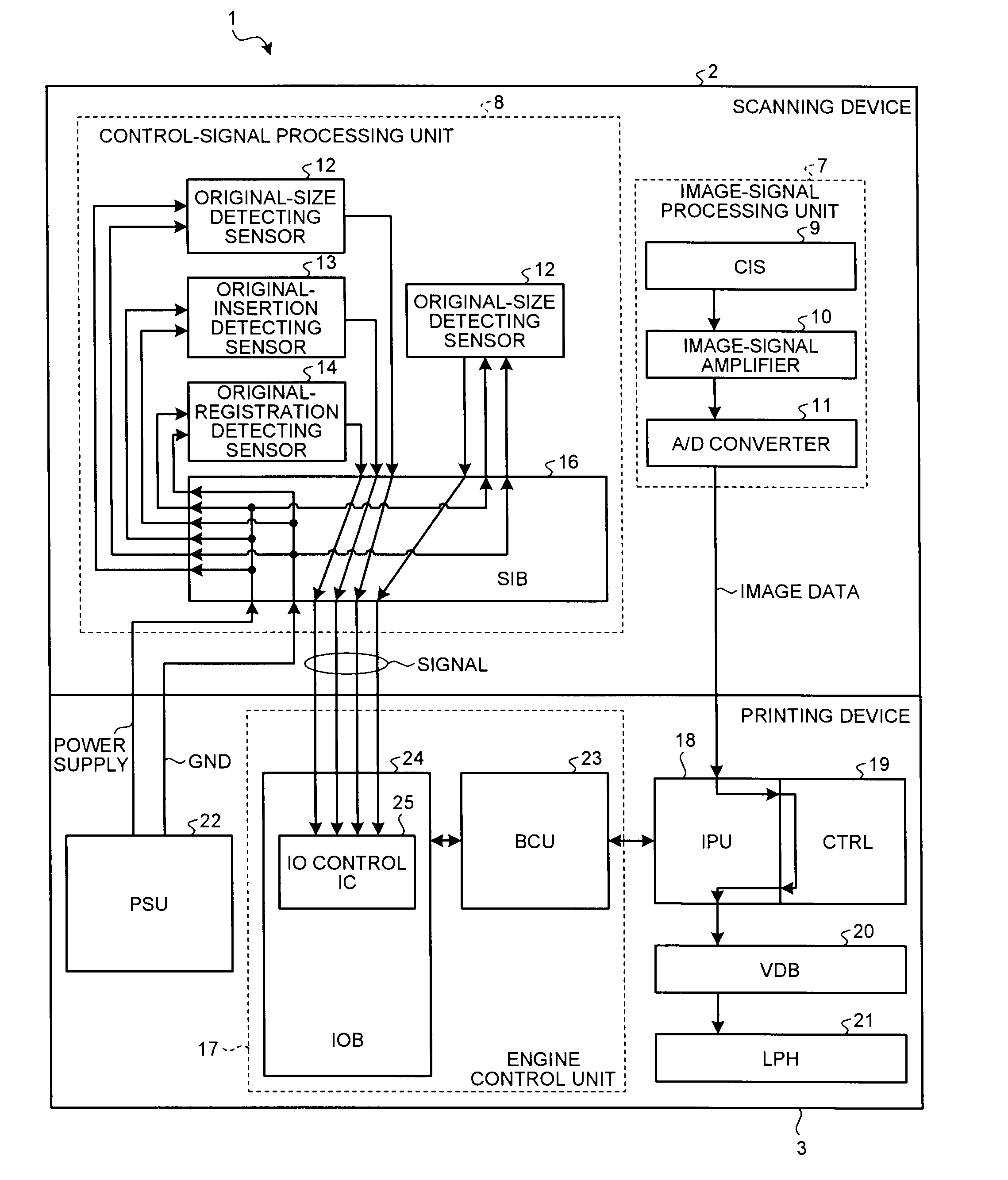
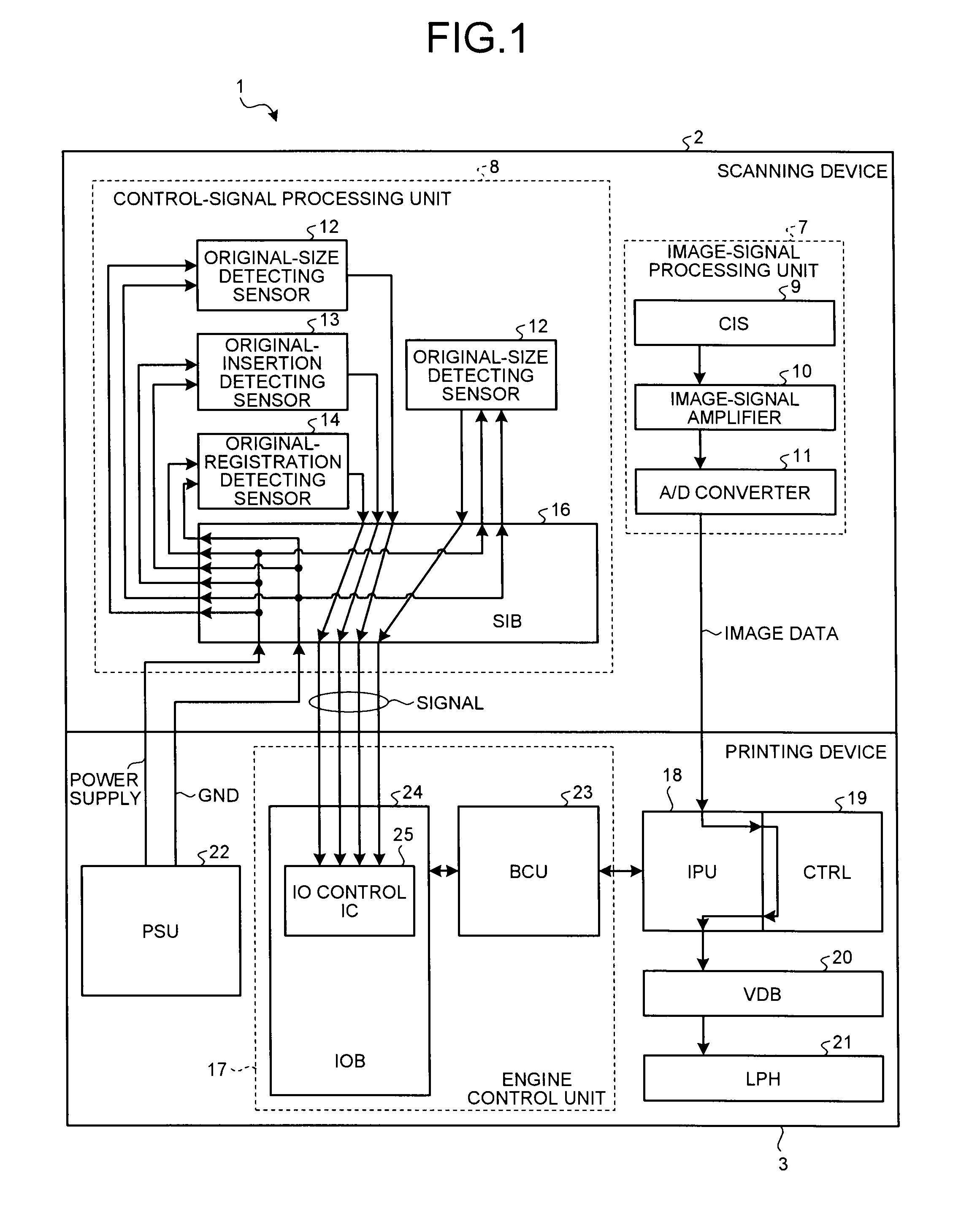
[0041]FIG. 1 is a block diagram of a copy machine 1 according to the present invention. The copy machine 1 includes a scanning device 2 and a printing device 3. Although the scanning device 2 and the printing device 3 are integrally arranged in FIG. 1, the scanning device 2 and the printing device 3 can be separately arranged depending on a request from a user.
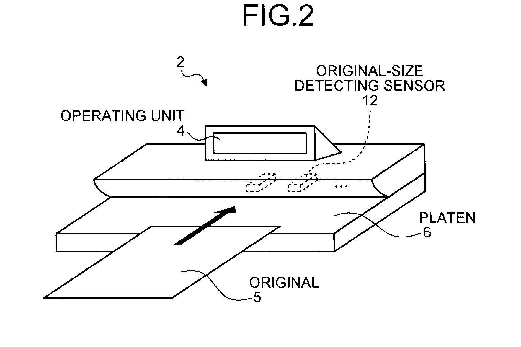
[0042]FIG. 2 is a schematic diagram of the scanning device 2. The scanning device 2 is an automatic document feeder scanner. When settings are entered by using an operating unit 4 and an original 5 is placed on a platen 6 such that the original 5 is inserted into a direction indicated by an arrow in FIG. 2, the original 5 is conveyed in that direction. Then, two original-size detecting sensors 12 detect a size of the original 5. The original-size detecting sensors 12 are arranged inside the scanning device 2. A contact image sensor (CIS) 9 then scans an image on the original 5. The scanning device 2 can be divided into two fun...
second embodiment
[0070]In the present invention, each of a scanning device and a printing device includes a low voltage differential signaling (LVDS) driver and an LVDS receiver. A signal is transmitted between the LVDS driver and the LVDS receiver.
[0071]In the second embodiment, description on components of a copy machine 31, except for the same components as those of the copy machine 1, is explained.
[0072]FIG. 6 is a block diagram of the copy machine 31. The image-signal processing unit 7, the IPU 18, the Ctrl 19, the VDB 20, the LPH 21, and the BCU 23 are not shown in FIG. 6, because the configurations of those are the same as those in the first embodiment, and therefore, the same explanations are not repeated.
[0073]The copy machine 31 includes a scanning device 32 and a printing device 33. Although the scanning device 32 and the printing device 33 are integrally arranged in FIG. 6, the scanning device 32 and the printing device 33 can be separately arranged depending on a request from a user.
[00...
third embodiment
[0102]In the third embodiment, description on components of a copy machine 51, except for the same components as those of the copy machine 31, is explained.
[0103]FIG. 13 is a block diagram of the copy machine 51. The image-signal processing unit 7, the IPU 18, the Ctrl 19, the VDB 20, the LPH 21, and the BCU 23 are not shown in FIG. 13, because the configurations of those are the same as those in the second embodiment.
[0104]The copy machine 51 includes the scanning device 52 and the printing device 53. Although the scanning device 52 and the printing device 53 are integrally arranged in FIG. 13, the scanning device 52 and the printing device 53 can be separately arranged depending on a request from a user.
[0105]The scanning device 52 includes the image-signal processing unit 7 and a control-signal processing unit 54. The control-signal processing unit 54 includes the two original-size detecting sensors 12, the original-insertion detecting sensor 13, the original-registration detecti...
PUM
 Abstract
Description
Claims
Application Information