Method and apparatus for providing an electrostatic chuck with reduced plasma penetration and arcing

a technology of electrostatic chuck and plasma, which is applied in the direction of chucks, mechanical equipment, manufacturing tools, etc., can solve the problems of arcing that forms particulate contaminants in the chamber, plasma damage to the substrate, and the electrostatic chuck or both. to achieve the effect of reducing plasma formation

Active Publication Date: 2009-02-05
APPLIED MATERIALS INC
View PDF21 Cites 47 Cited by
  • Summary
  • Abstract
  • Description
  • Claims
  • Application Information

AI Technical Summary

Benefits of technology

[0010]The present invention generally provides a method and apparatus for providing a fluid distribution element for an electrostatic chuck that reduces plasma formation and arcing within heat transfer fluid passages. One embodiment comprises a plate and a dielectric component, where the dielectric component is inserted into the plate. The plate is adapted to be positioned within a channel to define a plenum, wherein the dielectric component provides at least a portion of a fluid passage coupled to the plenum. A porous dielectric layer, formed upon the dielectric component, provides at least another portion of a fluid passage coupled to the plenum. In other embodiments, the fluid distribution element comprises various arrangements of components to define a fluid passage that does not provide a line-of-sight path from the support surface for a substrate to a plenum.

Problems solved by technology

The operation and service life of the electrostatic chuck is adversely affected by plasma formation in the gas passages.
Such plasma may damage the substrate, the electrostatic chuck or both.
Furthermore, plasma formation in a gas passage can lead to arcing that forms particulate contaminants in the chamber.
While the porous material provides protection against plasma formation, fabrication of such electrostatic chucks is difficult, time consuming and costly.

Method used


Image

  • Method and apparatus for providing an electrostatic chuck with reduced plasma penetration and arcing
  • Method and apparatus for providing an electrostatic chuck with reduced plasma penetration and arcing
  • Method and apparatus for providing an electrostatic chuck with reduced plasma penetration and arcing

Examples


Embodiment Construction

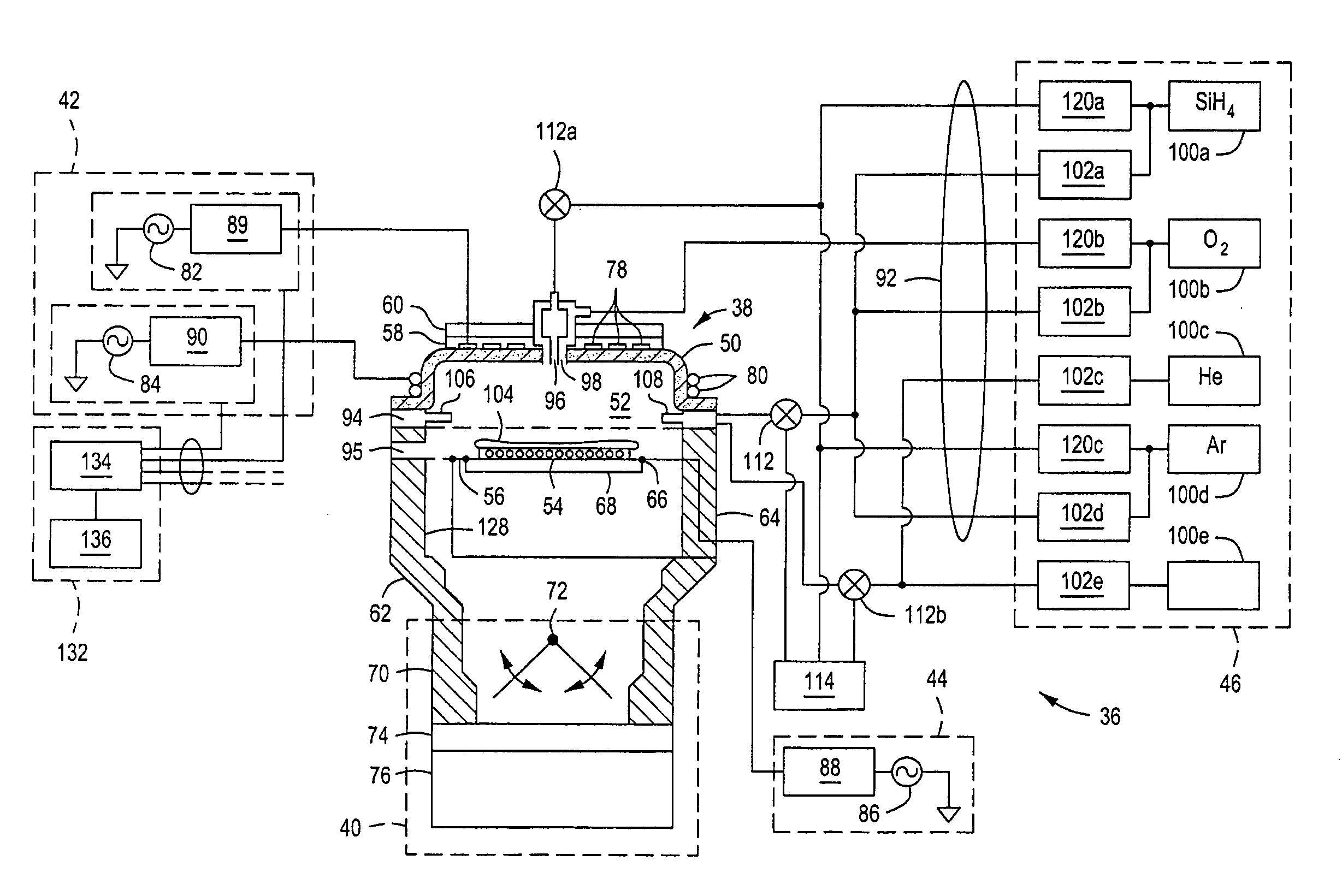
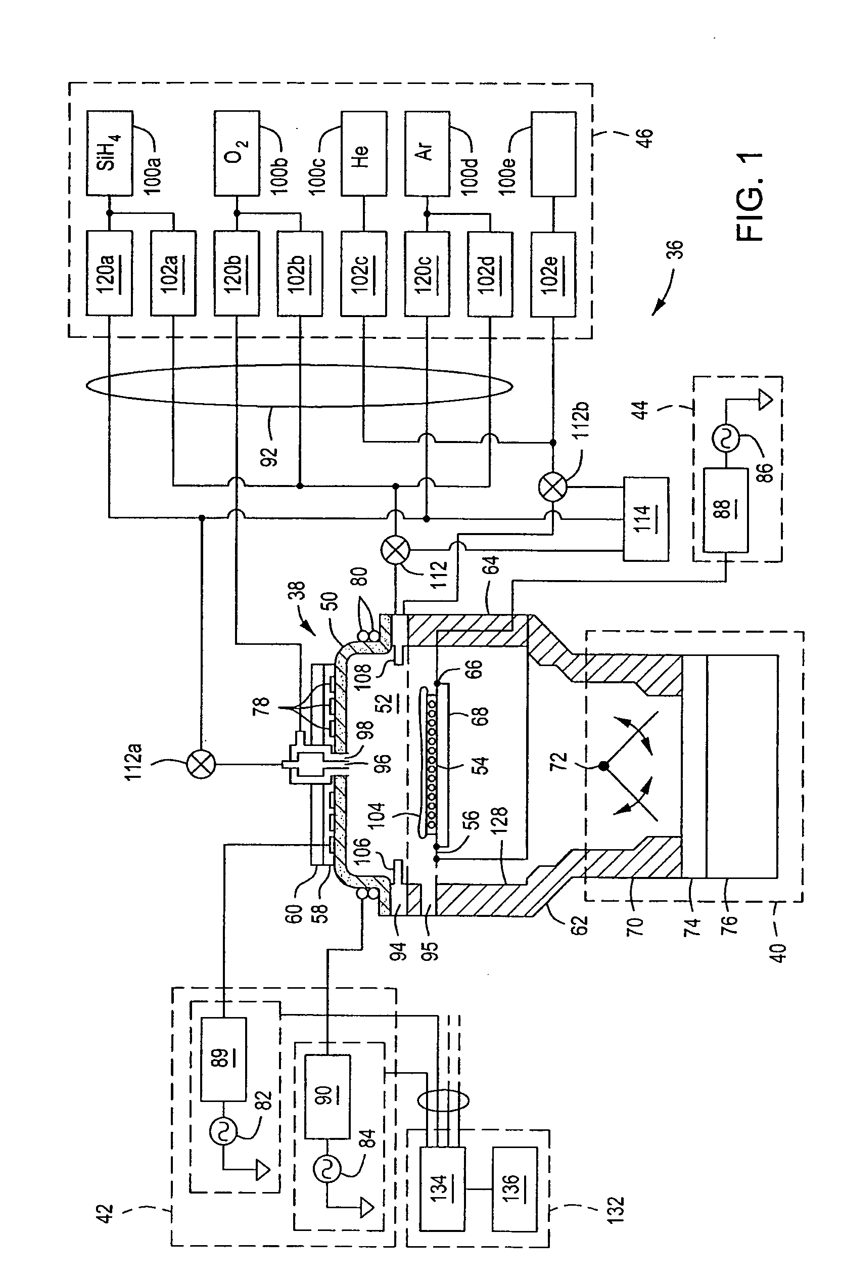
[0024]FIG. 1 illustrates a plasma-based substrate processing system 36 comprising an electrostatic chuck 68 according to various embodiments of the present invention. The plasma processing system 36 is used for temperature controlled processing of substrates, such as Silicon wafers, GaAs wafers and the like, while creating and maintaining a plasma environment in which to process the substrates. The plasma is created in the vicinity of the substrate for processing the substrate, and the temperature of the substrate is controlled using various techniques, such as, by supplying a heat transfer fluid to the back surface of the substrate. Although one embodiment of a plasma processing chamber is described illustratively in a high density plasma-chemical vapor deposition (HDP-CVD) system such as the 300 mm HDP-CVD Ultima X system available from Applied Materials, Inc. of Santa Clara, Calif., the invention has utility in other process chambers where plasma is used including physical vapor ...


PUM


Abstract

A method and apparatus for providing a fluid distribution element for an electrostatic chuck that reduces plasma formation and arcing within heat transfer fluid passages. One embodiment comprises a plate and a dielectric component, where the dielectric component is inserted into the plate. The plate is adapted to be positioned within a channel to define a plenum, wherein the dielectric component provides at least a portion of a fluid passage coupled to the plenum. A porous dielectric layer, formed upon the dielectric component, provides at least another portion of a fluid passage coupled to the plenum. In other embodiments, the fluid distribution element comprises various arrangements of components to define a fluid passage that does not provide a line-of-sight path from the support surface for a substrate to a plenum.

Description

CROSS-REFERENCE TO RELATED APPLICATIONS[0001]This application contains subject matter that is related to U.S. patent application Ser. No. ______, filed simultaneously herewith, entitled METHOD FOR REFURBISHING AN ELECTROSTATIC CHUCK WITH REDUCED PLASMA PENETRATION AND ARCING (Attorney Docket No. 11736US02 / AGS / IBSS), and application Ser. No. ______, filed simultaneously herewith, entitled METHOD OF MAKING AN ELECTROSTATIC CHUCK WITH REDUCED PLASMA PENETRATION AND ARCING, (Attorney Docket No. 11736US03 / AGS / IBSS). The aforementioned related patent applications are incorporated herein by reference in their entirety.BACKGROUND OF THE INVENTION[0002]1. Field of the Invention[0003]Embodiments of the present invention generally relate to equipment for performing semiconductor device fabrication, and more particularly, to an electrostatic chuck for supporting a semiconductor wafer during processing.[0004]2. Description of the Related Art[0005]Electrostatic chucks are widely used for providin...

Claims


Application Information

Patent Timeline
Patent Type & Authority Applications(United States)
IPC IPC(8): H01L21/683H01L21/67
CPCH01L21/6831Y10T279/23H01L21/6833
Inventor NARENDRNATH, KADTHALA RAMAYACHEN, XINGLONGGONDHALEKAR, SUDHIRLUBOMIRSKY, DMITRYRASHEED, MUHAMMADKAUSHAL, TONY
Owner APPLIED MATERIALS INC
Why Eureka
Try Eureka