Sound image localization control apparatus
Inactive Publication Date: 2009-02-05
SOVEREIGN PEAK VENTURES LLC
View PDF4 Cites 13 Cited by
Summary
Abstract
Description
Claims
Application Information
AI Technical Summary
This helps you quickly interpret patents by identifying the three key elements:
Problems solved by technology
Method used
Benefits of technology
[0016]As described above, according to the present invention, provided is a sound image localization control apparatus which allows a plurality of users to variably adjust the acoustical effect individually without diminishing the sound image localization effect of a sound reproducing apparatus which performs sound image localization for the plurality of users.
Problems solved by technology
However, reproducing characteristics of such an apparatus are designed for one user and accordingly an ideal acoustical effect is not exerted on other users excluded from consideration.
Method used
Image
Click on the blue label to locate the original text in one second.
Reading with bidirectional positioning of images and text.
Examples
first embodiment
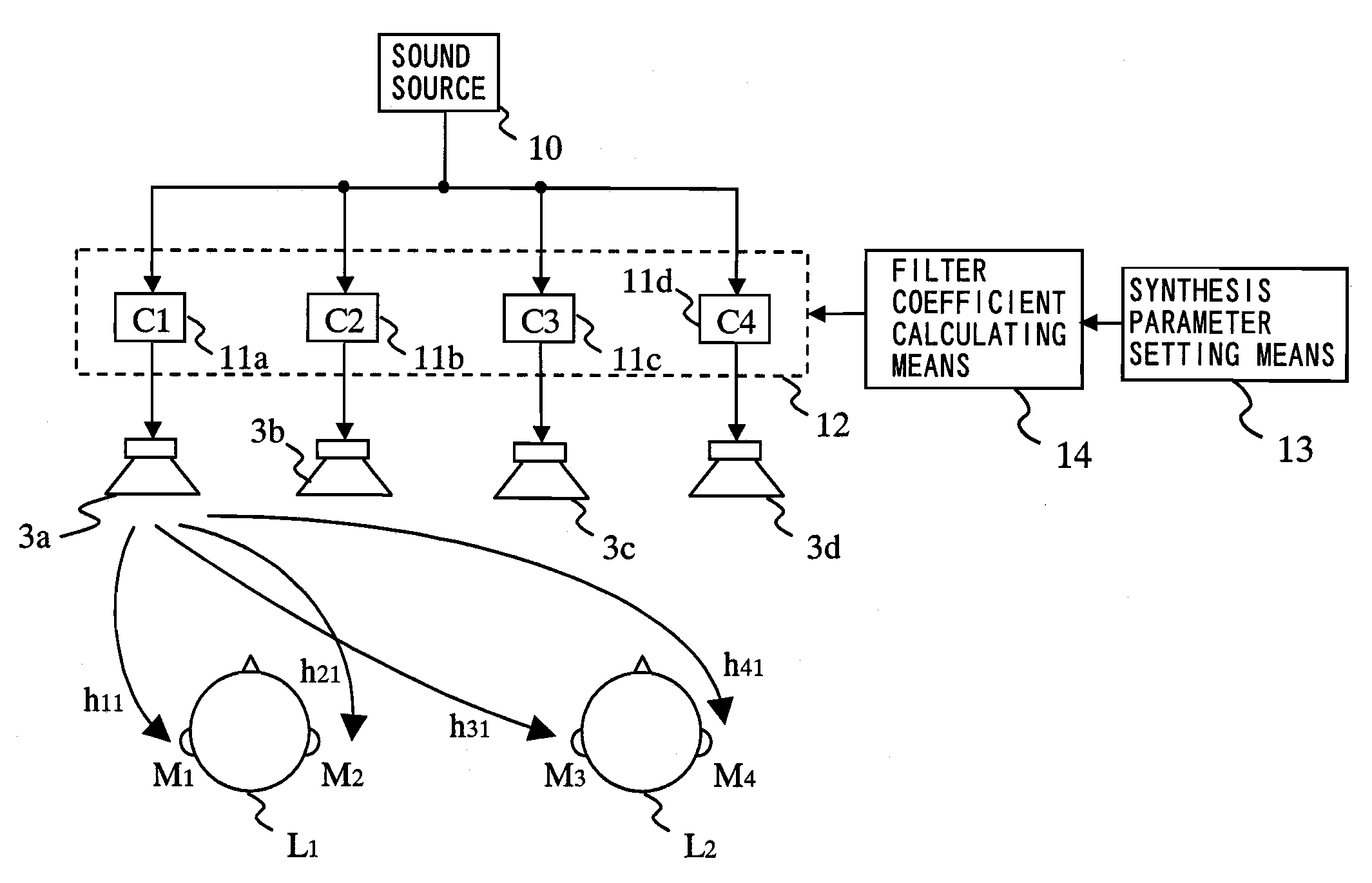
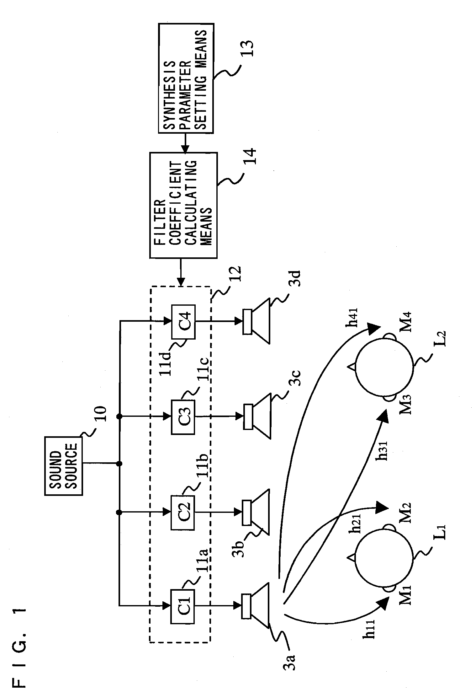
[0050]FIG. 1 is a schematic view showing a configuration of a sound image localization control apparatus according to a first embodiment. The sound image localization apparatus according to the present embodiment allows two users to simultaneously share a common sound image localization effect and to individually adjust sound volumes. The sound image localization control apparatus mainly comprises a sound source 10, speakers 3a, 3b, 3c, and 3d, a control processing section 12, synthesis parameter setting means 13, and filter coefficient calculating means 14. The synthesis parameter setting means 13 and the filter coefficient calculating means 14 according to the present embodiment correspond to processing characteristic setting means. The control processing section 12 corresponds to controlling means, and the speakers 3a, 3b, 3c, and 3d correspond to sound reproducing means.
[0051]The sound source 10 may be a monophonic sound source, one channel signal source among multi-channel soun...
second embodiment
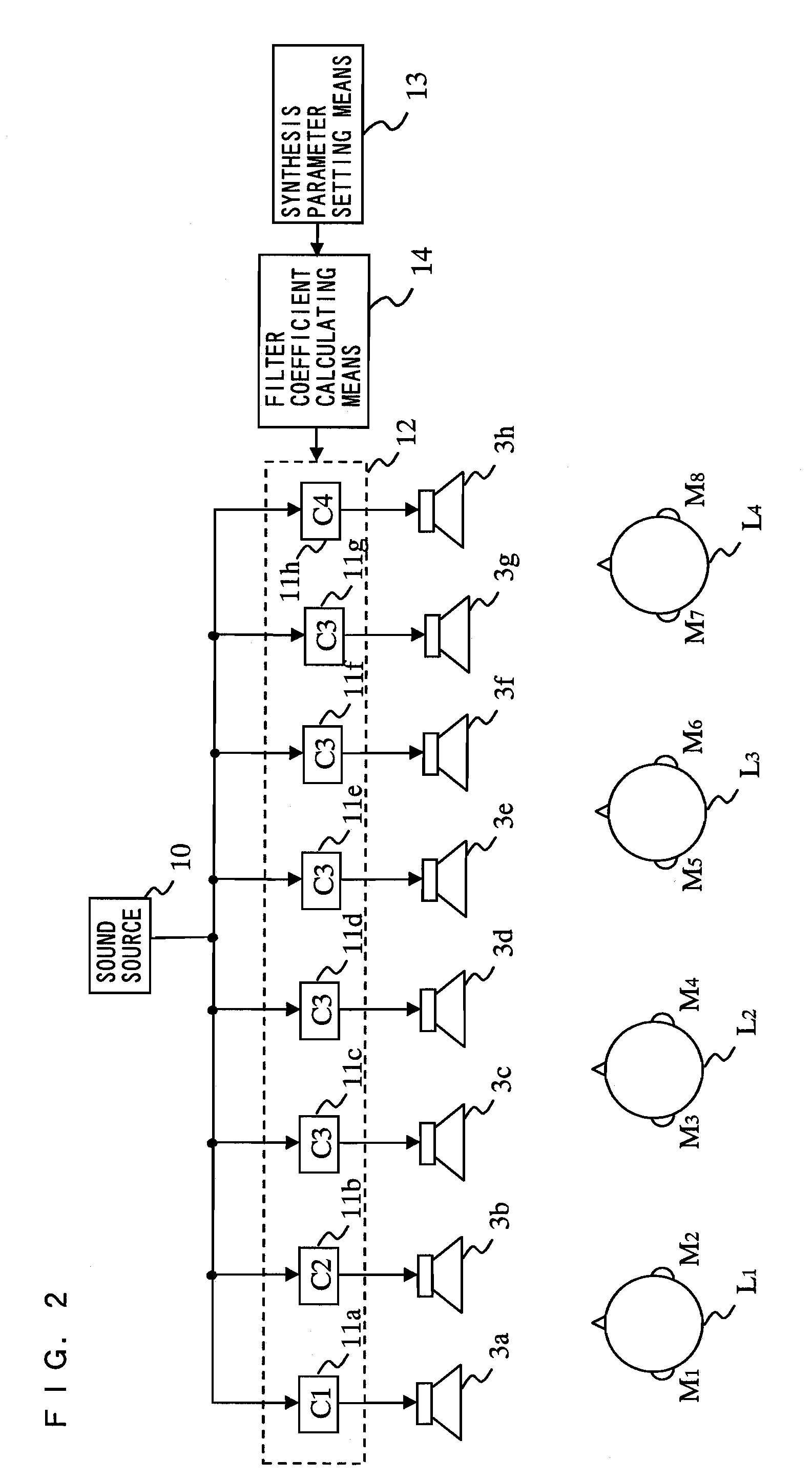
[0071]FIG. 4 is a schematic view showing a configuration of a sound image localization control apparatus according to a second embodiment. The sound image localization control apparatus allows two users to share a common sound image localization effect and to individually adjust sound volumes. As shown in FIG. 4, the sound image localization control apparatus comprises the speakers 3a, 3b, 3c, and 3d, the sound source 10, control digital filters 11a, 11b, 11c, 11d, 11e, 11f, 11g and 11h, the synthesis parameter setting means 13, gain units 16a, 16b, 16c, 16d, 16e, 16f, 16g, and 16h, and the adders 15a, 15b, 15c, and 15d. In FIG. 4, identical components to those in the first embodiment will bear identical reference characters and detailed descriptions thereof will be omitted.
[0072]An output from the sound source 10 is inputted to the gain units 16a, 16b, 16c, 16d, 16e, 16f, 16g, and 16h, and variable adjustment of a gain is allowed. Outputs from the gain units 16a, 16b, 16c, 16d, 16e...
PUM
Abstract
Provided is a sound image localization control apparatus for allowing, when sound is reproduced so as to perform sound image localization for a plurality of users, each of the plurality of users to variably adjust an acoustical effect individually without diminishing a sound image localization effect. The sound image localization control apparatus comprises: processing characteristic setting means (13; 14) for setting a processing characteristic in controlling means such that acoustic transfer functions for at least two predetermined positions each represent a desired characteristic; controlling means (12) for receiving an acoustic signal and the processing characteristic which is set by the processing characteristic setting means and performing signal processing; and sound reproducing means (3) for receiving an output from the controlling means.
Description
TECHNICAL FIELD[0001]The present invention relates to a sound image localization control apparatus.BACKGROUND ART[0002]In recent years, contents such as a movie and music recorded on a DVD or the like have become widely used, and therefore a reproducing apparatus capable of providing an ideal sense of localization and an ideal sense of a sound field while reproducing multi-channel audio in a living room or in a vehicle has been proposed. However, reproducing characteristics of such an apparatus are designed for one user and accordingly an ideal acoustical effect is not exerted on other users excluded from consideration. Thus, an apparatus to solve such a problem is proposed in patent document 1. Hereinafter, a sound reproducing apparatus disclosed in patent document 1 will be described with reference to drawings.[0003]FIG. 9 shows a sound reproducing apparatus 1, which is disclosed in patent document 1, provided in a front seat of a vehicle. To be more specific, by making two passen...
Claims
Application Information
Patent Timeline
Application Date:The date an application was filed.
Publication Date:The date a patent or application was officially published.
First Publication Date:The earliest publication date of a patent with the same application number.
Issue Date:Publication date of the patent grant document.
PCT Entry Date:The Entry date of PCT National Phase.
Estimated Expiry Date:The statutory expiry date of a patent right according to the Patent Law, and it is the longest term of protection that the patent right can achieve without the termination of the patent right due to other reasons(Term extension factor has been taken into account ).
Invalid Date:Actual expiry date is based on effective date or publication date of legal transaction data of invalid patent.
Patent Type & Authority Applications(United States)