Directional Sound Wave Radiator

a radiator and sound wave technology, applied in the direction of transducer details, electrical transducers, instruments, etc., can solve the problems of limited propagation distance, low sound wave energy concentration, and hardly achievable using conventional loudspeakers, so as to reduce the overall size of the loudspeaker of the present invention. , the effect of increasing the sound pressure level on the sound axis of the present invention

Inactive Publication Date: 2009-02-05
BEIJING WAVE ENERGY TECH DEVMENT
View PDF8 Cites 7 Cited by
  • Summary
  • Abstract
  • Description
  • Claims
  • Application Information

AI Technical Summary

Benefits of technology

[0004]In one respect, the present invention aims to provide a directional sound wave radiator, which differs from conventional loudspeaker structure in that it radiates sound wave as a narrow beam of wave so that it can realize more concentrated beam of sound energy than conventional loudspeakers, while it can realize smaller size to facilitate its movement.
[0010]The directional sound radiator of the present invention has the advantage that it has a relatively small sound wave radiation angle at its outlet end so that the sound wave energy is more concentrated for propagation over longer distance. In addition, it has a smaller overall size of loudspeaker, which is suitable for being included in a movable station for broadcasting high-intensity sound. With the directional sound radiator of the present invention, sound wave energy is concentrated on the sound axis. The sound pressure level on the sound axis of the loudspeaker of the present invention can be increased with respect to that of other loudspeakers by about 10-15 dB, with its sound beam range (−6 dB) being kept within ±15°. Thus, sound wave can be concentrated for longer propagation.

Problems solved by technology

Such a structure has the defect that its sound wave radiation angle at the output end is large, so the sound wave energy is not concentrated and the propagation distance is limited.
For long distance and / or high-intensity broadcasting, energy must be concentrated in a small range, which can hardly be achieved using conventional loudspeakers.

Method used


Image

  • Directional Sound Wave Radiator
  • Directional Sound Wave Radiator
  • Directional Sound Wave Radiator

Examples


Embodiment Construction

[0014]The present invention is described in detail below with reference to its specific embodiments.

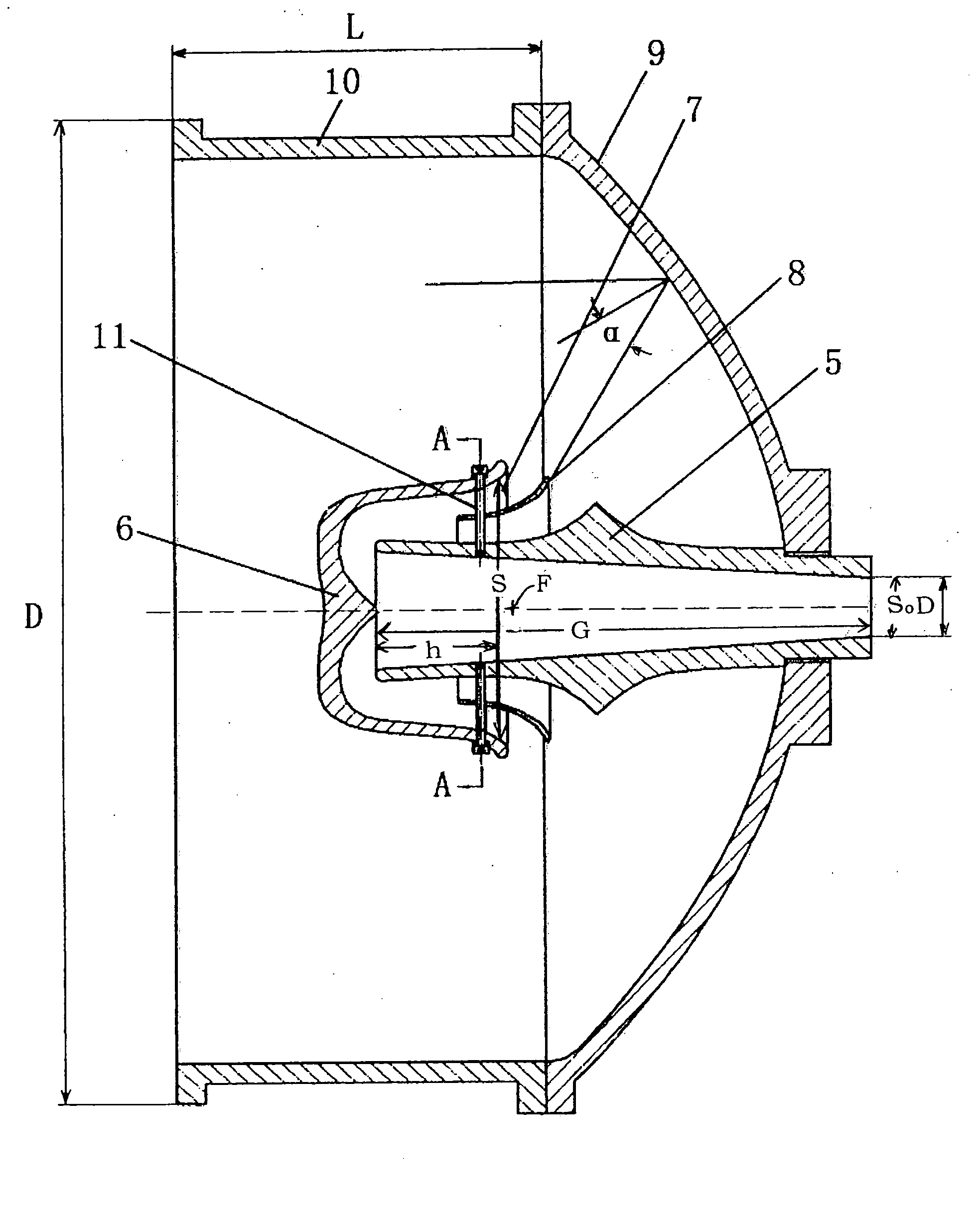
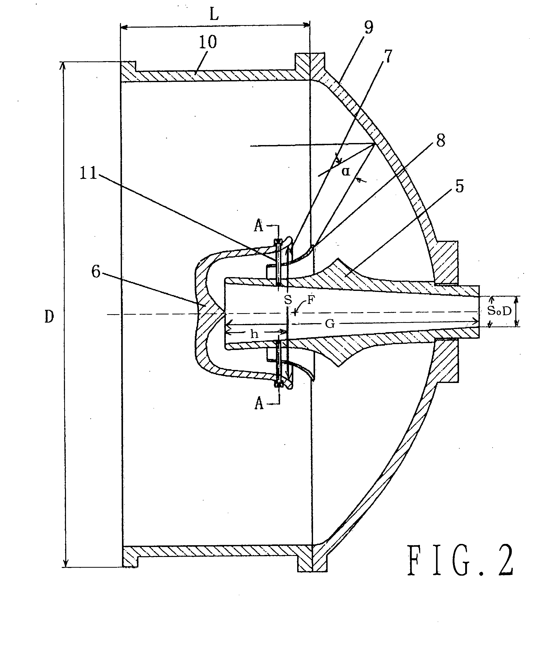
[0015]As shown in FIG. 2, a directional sound wave radiator of an embodiment of the present invention comprises a sound transmission duct 5, a reverser 6, an annular director 8, a parabolic reflector 9, and a straight tubular loudspeaker cylinder 10. Sound transmission duct 5 is arranged on the axis of parabolic reflector 9. Straight tubular loudspeaker cylinder 10 is connected to parabolic reflector 9. Reverser 6 is provided within straight tubular loudspeaker cylinder 10 and is arranged at the end of sound transmission duct 5. The outlet end of reverser 6 has an annular section, which is perpendicular to the axis of parabolic reflector 9 and is positioned approximately at the focus F of parabolic reflector 9. Annular director 8 is mounted around sound transmission duct 5 and at the outlet end of reverser 6 to define said annular section at the outlet of reverser 6.

[0016]In an embodi...


PUM


Abstract

The present invention belongs to the field of loudspeaker and relates to directional sound wave radiator comprising a sound transmission duct, a reverser, an annular director, a parabolic reflector, and a straight tubular loudspeaker cylinder. The sound transmission duct is mounted substantially coaxially with said parabolic reflector. The straight tubular loudspeaker cylinder is connected to said parabolic reflector. The reverser is provided inside said straight tubular loudspeaker cylinder and at the outlet end of said sound transmission duct; the outlet end of said reverser has an annular section, which is substantially perpendicular to the axis of said parabolic reflector and is positioned substantially at the focus of said parabolic reflector. The annular director is mounted around said sound transmission duct and at the outlet end of said reverser to define an annular shape of the outlet end of said reverser. The reverser and said annular director are fixed to said sound transmission duct by supporting screws.

Description

REFERENCE TO RELATED APPLICATIONS[0001]This application claims foreign priority benefits from Chinese Patent Application No. 200710119916.9, filed Aug. 3, 2007.FIELD OF THE INVENTION[0002]The present invention relates to directional sound wave radiator, particularly to a directional sound wave radiator for use in high power, long distance and high intensity sound broadcasting. The present invention belongs to the technical field of loudspeaker.BACKGROUND OF THE INVENTION[0003]Conventionally, most loudspeaker horns have exponential curve, suspension line curve, or conical line shapes. FIG. 1 shows a conventional loudspeaker horn having an exponential curve shape. As shown in FIG. 1, such a conventional loudspeaker has a sound-generating head 1, an exponential horn 2, an exponential horn outlet section 3, and a reverser section 4. The loudspeaker horn works by utilizing a horn curve to provide certain resistance to the sound source (sound-generating head) to obtain an optimal efficien...

Claims


Application Information

Patent Timeline
Patent Type & Authority Applications(United States)
IPC IPC(8): H04R11/02
CPCH04R1/345
Inventor XI, BAOSHU
Owner BEIJING WAVE ENERGY TECH DEVMENT
Why Eureka
Try Eureka