Unlock instant, AI-driven research and patent intelligence for your innovation.

Hydrostatic gas bearing, rotator and CT scanner

Inactive Publication Date: 2009-02-05
NTN CORP
View PDF15 Cites 14 Cited by
  • Summary
  • Abstract
  • Description
  • Claims
  • Application Information

AI Technical Summary

Benefits of technology

[0012]An object of the present invention is to provide a hydrostatic gas bearing simplifying adjustment of a clearance between a rotor and a radial bearing pad.
[0013]Another object of the present invention is to provide a rotator allowing compactification of a rotor thereby enabling weight reduction of the rotor, reduction of a moment of inertia etc.

Problems solved by technology

In this state, it is extremely difficult to adjust the bearing clearance to an ideal quantity with a screw or the like mounted on the outer periphery of the ball stud at the back of the radial bearing pad.

Method used


Image

  • Hydrostatic gas bearing, rotator and CT scanner
  • Hydrostatic gas bearing, rotator and CT scanner
  • Hydrostatic gas bearing, rotator and CT scanner

Examples


first embodiment

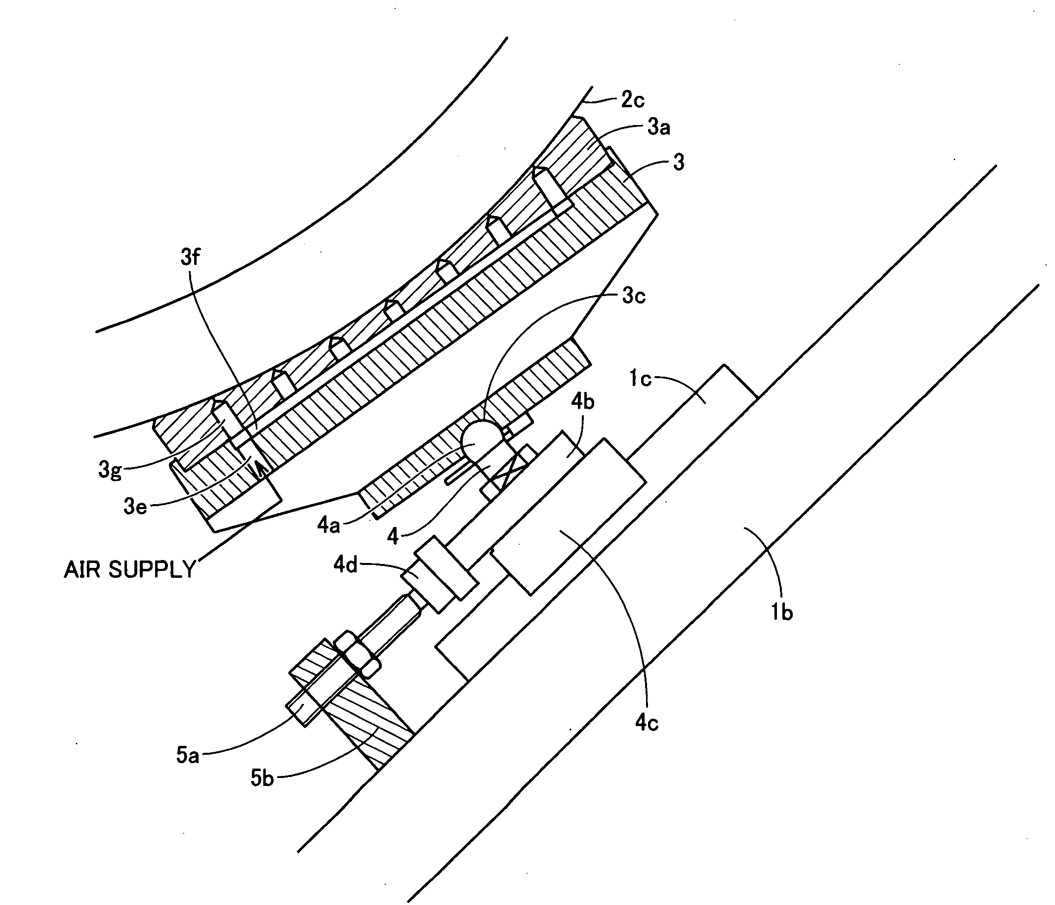
[0049]As shown in FIG. 1, a hydrostatic gas bearing according to a first embodiment of the present invention is provided with a pad bearing portion 3a, to be opposed to an outer peripheral surface 2c of a rotating shaft. A radial bearing pad 3 radially supports the rotating shaft with pad bearing portion 3a on outer peripheral surface 2c of the rotating shaft. The surface of pad bearing portion 3a opposed to outer peripheral surface 2c has a curvature substantially identical to that of outer peripheral surface 2c. In other words, the surface of pad bearing portion 3a opposed to outer peripheral surface 2c has a radius of curvature identical to that of outer peripheral surface 2c or larger than that of outer peripheral surface 2c by a bearing clearance between radial bearing pad 3 and outer peripheral surface 2c. A recess 3c is formed on a side of radial bearing pad 3 opposite to the side provided with pad bearing 3a. Recess 3c is in the form of a spherical surface. Recess 3c may alt...

second embodiment

[0088]A hydrostatic gas bearing according to a second embodiment of the present invention is basically similar in structure to the aforementioned hydrostatic gas bearing according to the first embodiment. The hydrostatic gas bearing according to the second embodiment is different from that according to the first embodiment in a point that a coupling portion coupling a radial bearing pad 3 to a linear motion guide 1c serving as a moving member has a structure shown in FIG. 7. More specifically, the coupling portion is constituted of a hinge 7. Hinge 7 is arranged so as to render radial bearing pad 3 movable only in the circumferential direction of an outer peripheral surface 2c.

[0089]In other words, hinge 7 supports radial bearing pad 3 to be freely inclinable with respect to linear motion guide 1c in the circumferential direction of a rotor. Therefore, radial bearing pad 3 is movable in the circumferential direction of the rotor while varying the inclination with respect to linear ...


PUM


Abstract

A hydrostatic gas bearing capable of easily adjusting a clearance between a rotor and a radial bearing pad is provided. This hydrostatic gas bearing comprises a radial bearing pad radially supporting a rotor, a linear motion guide moving the radial bearing pad and a ball stud swingably coupling the radial bearing pad to the linear motion guide. The linear motion guide moves the radial bearing pad in a direction intersecting with a direction connecting the center of rotation of the rotor and the ball stud with each other. The quantity of adjustment in movement of the radial bearing pad caused by the linear motion guide is larger than the quantity of change in the clearance between the outer peripheral surface of the rotor and the radial bearing pad, whereby a small quantity of the bearing clearance can be precisely adjusted.

Description

BACKGROUND OF THE INVENTION[0001]1. Field of the Invention[0002]The present invention relates to a hydrostatic gas bearing, a rotator and a CT scanner, and more particularly, it relates to a hydrostatic gas bearing supporting a rotor, a rotator supported by this hydrostatic gas bearing and a CT scanner employing this rotator.[0003]2. Description of the Background Art[0004]In the field of roller bearings generally used for supporting rotors, hydrostatic gas bearings are increasingly employed in order to implement high-speed / high-precision rotation, low noise, low vibration, long life etc.[0005]For example, a CT scanner in the field of medical diagnostic image formation has a rotating shaft loaded with a radiation source or the like. National Patent Publication Gazette No. 2004-528113 discloses an example of supporting a rotating shaft of a CT scanner with a hydrostatic gas bearing in order to 1) increase the speed of the CT scanner for reducing the scanning time, 2) obtain a silent o...

Claims


Application Information

Patent Timeline
IPC IPC(8): F16C32/06F16F15/023
CPCF16C32/0666
Inventor FUJIKAWA, YOSHIOHIRATA, JUNICHI
Owner NTN CORP