Optical transceiver with an optical sub-assembly supporter by a holder and a cover

a technology of optical transceivers and supporters, applied in the field of pluggable optical transceivers, can solve problems such as easy misalignment of sub-assemblies

Inactive Publication Date: 2009-02-05
SUMITOMO ELECTRIC IND LTD
View PDF22 Cites 10 Cited by
  • Summary
  • Abstract
  • Description
  • Claims
  • Application Information

AI Technical Summary

Benefits of technology

[0013]The support by the holder and the subassembly cover for the subassembly may align the subassembly in a plane perpendicular to the optical axis of the subassembly, while, the pressing the flange by the holder and the subassembly cover against the saddle of the lower frame may align the subassembly along the optical axis of the subassembly. Thus, the subassembly is not only securely supported by the holder and the subassembly cover but also automatically aligned with respect to the optical axis.

Problems solved by technology

However, when such an optical subassembly with the box-shaped body and the sleeve portion is assembled and aligned within the housing, misalignment of the subassembly easily occurs due to an avoidable moment inevitably induced by the enlarged body.

Method used


Image

  • Optical transceiver with an optical sub-assembly supporter by a holder and a cover
  • Optical transceiver with an optical sub-assembly supporter by a holder and a cover
  • Optical transceiver with an optical sub-assembly supporter by a holder and a cover

Examples


modified embodiment

[0052]FIG. 9 illustrates a modified holder 117 according to another embodiment of the invention. This holder 117, similar to the previous holder 17 shown in FIG. 5, integrally builds a TOSA side 117a, a ROSA side 117b and a plurality of latch fingers 117e. The TOSA side 117a provides a pedestal portion 117c with a concave surface 117f that comes in contact with the extending cylinder 15b of the TOSA by two lines, and the flange mount 117d in a forward side of the pedestal portion 117e. A feature of this holder 117 distinguishable from the previous holder 17 is that the pedestal portion 117c forms a plurality of projections 117l in the bottom thereof.

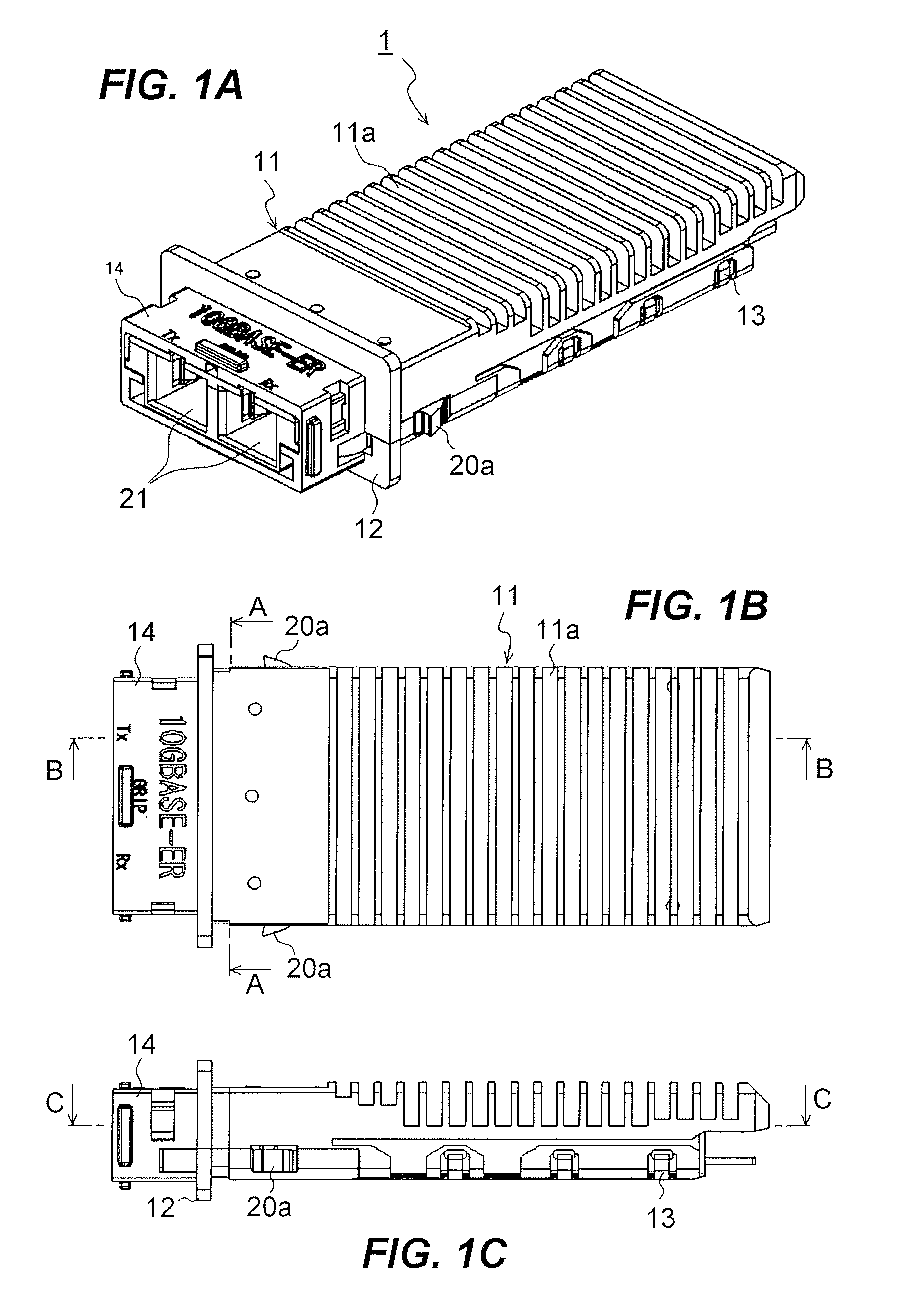
[0053]FIG. 10A is a cross section taken along the ling A-A shown in FIG. 1B, while FIG. 10B is a cross section taken along the line C-C in FIG. 1C, each illustrating the modified holder 117. As shown in FIG. 10A, the holder 117 supports the extending cylinder 15b of the TOSA 16, while, the TOSA cover 18 presses the extending cylinder 15b...


PUM


Abstract

An optical transceiver is disclosed, in which an optical subassembly maybe assembled within a housing without degrading an optical coupling efficiency between a semiconductor optical device in the subassembly and an optical fiver in an external optical connected that is mated with the housing of the transceiver. The subassembly comprises a sleeve portion and a body portion that installs the optical device therein. The subassembly is assembled in the housing such that the sleeve portion thereof is put between the holder and the cover. The holder and the cover each provides a concave surface that comes in contact with the sleeve portion only by two lines in parallel to the optical axis of the subassembly when the sleeve portion is set within the concave surface.

Description

CROSS REFERENCE TO RELATED APPLICATIONS[0001]The present is closely related to a prior application, Ser. No. of which is 12 / 076,099, filed on Mar. 13, 2008, entitled “Optical transceiver with mechanism to dissipate heat efficiently without affecting optical coupling condition,” which is incorporated herein by reference in its entirety.BACKGROUND OF THE INVENTION[0002]1. Field of the Invention[0003]The present invention relates to a pluggable optical transceiver.[0004]2. Related Prior Art[0005]A conventional optical transceiver, such as shown in the U.S. Patent Application published as US 2006 / 0093287A, mates with an LC-type optical connector and provides an optical sub-assembly with a pair of flanges in the outer surface of the sleeve portion and a housing comprising an upper and lower frames both forming an U-shaped saddle inside of the housing. The subassembly may be assembled with the housing by an arrangement where the U-shaped saddle in both frames sets a portion between the fl...

Claims


Application Information

Patent Timeline
Patent Type & Authority Applications(United States)
IPC IPC(8): G02B6/26
CPCG02B6/4201G02B6/4292G02B6/4246
Inventor OKI, KAZUSHIGEKURASHIMA, HIROMI
Owner SUMITOMO ELECTRIC IND LTD
Why Eureka
Try Eureka