
Image forming apparatus, method of controlling same, and program

a technology of image forming apparatus and control method, which is applied in the direction of electrographic process apparatus, instruments, projectors, etc., can solve the problems of high system cost, time and trouble, and difficulty in “time- and trouble-saving, simple and accurate adjustment” and achieve the effect of simple and accurate adjustmen

Inactive Publication Date: 2009-02-05
SONY CORP
View PDF42 Cites 8 Cited by
  • Summary
  • Abstract
  • Description
  • Claims
  • Application Information

AI Technical Summary

Benefits of technology

[0009]This manner of adjusting the brightness on the screen requires a lot of time and effort on the part of the user and a high system cost. That is, the achievement of “daily operations with little need for human labor” and “time- and trouble-saving, simple and accurate adjustment” is difficult with the above existing method of adjusting the brightness on the screen.
[0010]The present invention addresses the above-identified, and other problems associated with existing methods and apparatuses, and makes it possible to achieve “daily operations with little need for human labor” and “time- and trouble-saving, simple and accurate adjustment” in connection with the adjustment of the brightness on the screen.
[0013]As described above, according to the present invention, the brightness on the image-projected object can be adjusted. In particular, the present invention makes it possible to achieve “daily operations with little need for human labor” and “time- and trouble-saving, simple and accurate adjustment” in connection with such adjustment.

Problems solved by technology

This manner of adjusting the brightness on the screen requires a lot of time and effort on the part of the user and a high system cost.
That is, the achievement of “daily operations with little need for human labor” and “time- and trouble-saving, simple and accurate adjustment” is difficult with the above existing method of adjusting the brightness on the screen.

Method used


Image

  • Image forming apparatus, method of controlling same, and program
  • Image forming apparatus, method of controlling same, and program
  • Image forming apparatus, method of controlling same, and program

Examples


Embodiment Construction

[0021]Hereinafter, an embodiment of the present invention will be described. Correspondence between the constituent features of the present invention as recited in the appended claims and specific examples described in the present specification and the accompanying drawings is exemplified as follows. Note that this preliminary description is meant to confirm that specific examples that support the present invention recited in the appended claims are described in the specification and the accompanying drawings. Therefore, even if there is a specific example that is described in the specification or the accompanying drawings but which is not described in this preliminary description as corresponding to any constituent feature of the present invention, that does not mean that this specific example does not correspond to any constituent feature. Conversely, even if a certain specific example is described in this preliminary description as corresponding to a certain constituent feature o...


PUM


Abstract

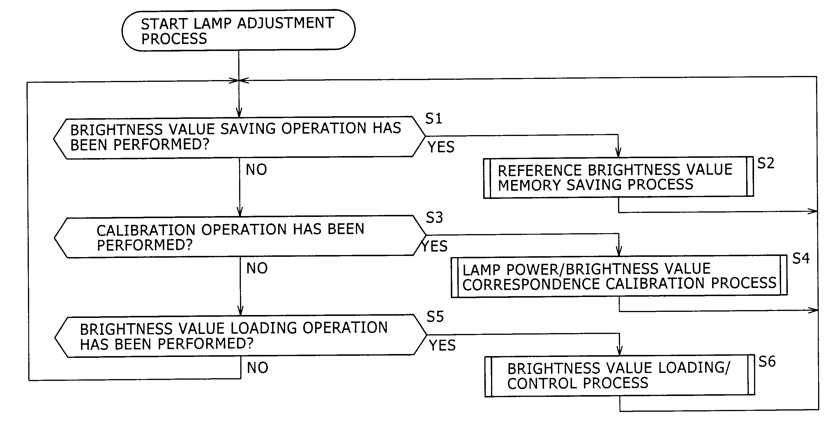
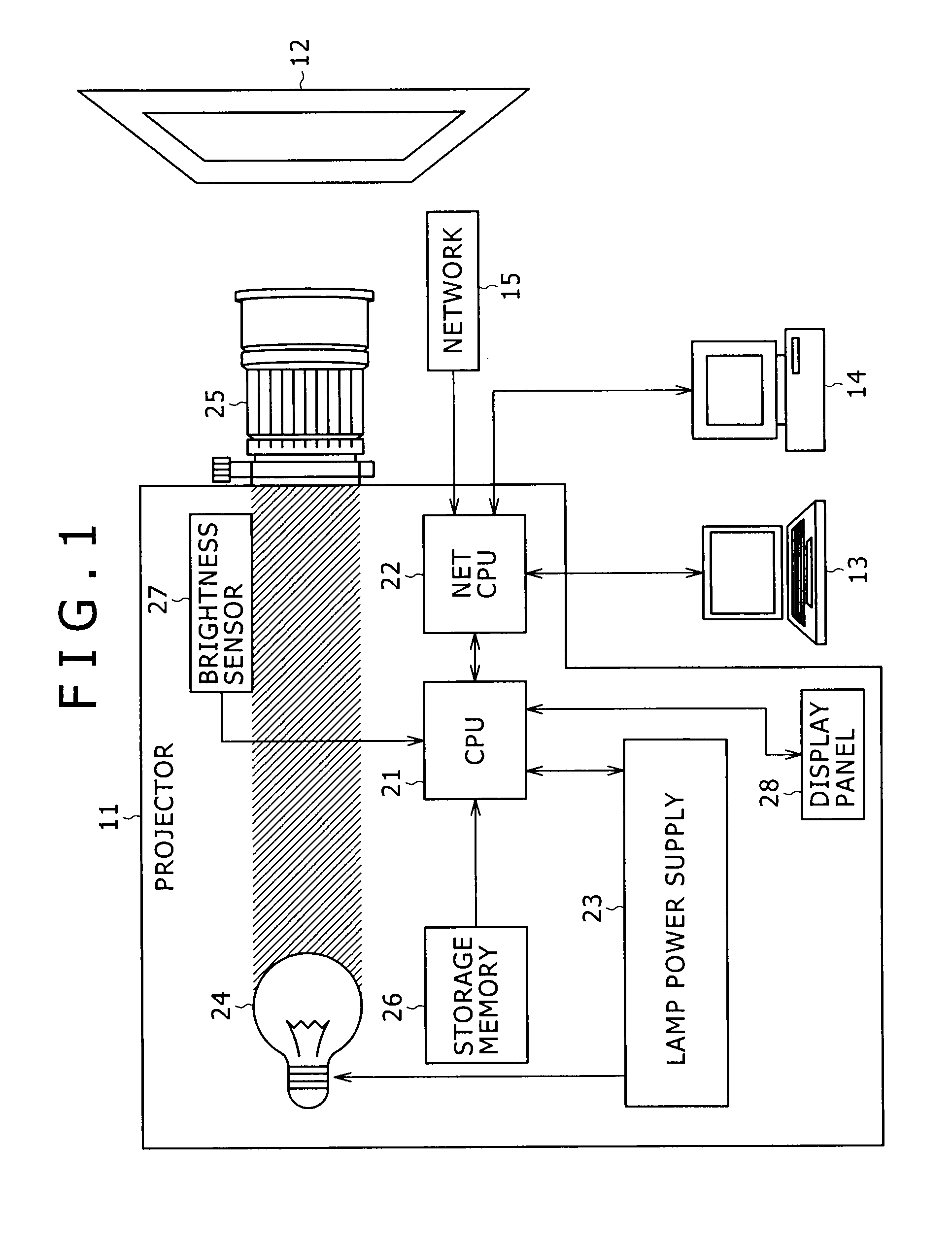
Disclosed herein is an image forming apparatus that emits a beam corresponding to an image onto an image-projected object to allow the image to be formed thereon. The apparatus includes: a lamp; a lamp power supply; a lens; a brightness sensor that measures a lamp brightness; a memory that stores, as a reference brightness value, the lamp brightness measured at a first time when brightness of the beam on the image-projected object has reached a target value; and a control circuit. At a second time, the control circuit performs first control of generating or updating and storing correspondence information. At a third time, the control circuit performs second control of identifying a level of an output power of the lamp power supply corresponding to the reference brightness value, and driving the lamp power supply with the identified level of the output power.

Description

CROSS REFERENCES TO RELATED APPLICATIONS[0001]The present invention contains subject matter related to Japanese Patent Application JP 2007-203475, filed in the Japan Patent Office on Aug. 3, 2007, the entire contents of which being incorporated herein by reference.BACKGROUND OF THE INVENTION[0002]1. Field of the Invention[0003]The present invention relates to an image forming apparatus, a method of controlling the same, and a program. In particular, the present invention relates to an image forming apparatus that allows brightness on a screen to be adjusted easily, a method for controlling the same, and a program.[0004]2. Description of the Related Art[0005]In the past, video contents, such as movies in movie theaters, were commonly projected by a film projector or the like on a screen.[0006]In recent years, with the development of the digitization technology for the video contents, study in and development of so-called digital cinema technology have been continuing. The digital cin...

Claims


Application Information

Patent Timeline
Patent Type & Authority Applications(United States)
IPC IPC(8): G03G15/043
CPCG03B21/00
Inventor OKA, DAIZO
Owner SONY CORP
Learn More