Information processing system, information processing device, and information processing method

Inactive Publication Date: 2009-02-05
RICOH KK
View PDF14 Cites 301 Cited by
  • Summary
  • Abstract
  • Description
  • Claims
  • Application Information

AI Technical Summary

Benefits of technology

[0011]It is an object of the present invention to at least

Problems solved by technology

However, according to the technique described in Japanese Patent Application Laid-open No. 2006-173948, while the user can determine that a printable image forming apparatus is at a relatively near distance when the client terminal receives the beacon, the user cannot naturally determine visually where the image forming apparatus is actually present.
Further, according to

Method used


Image

  • Information processing system, information processing device, and information processing method
  • Information processing system, information processing device, and information processing method
  • Information processing system, information processing device, and information processing method

Examples


first embodiment

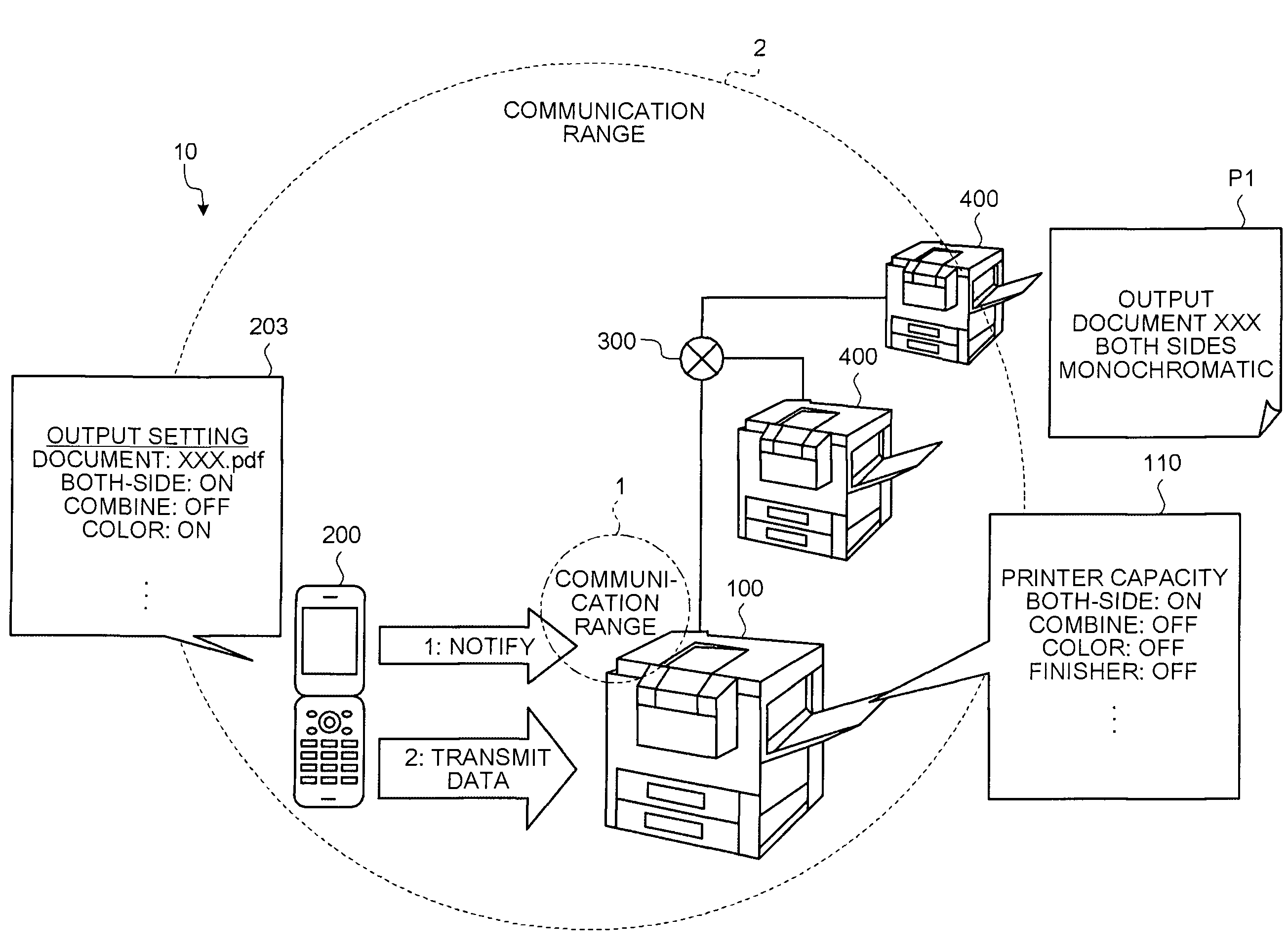
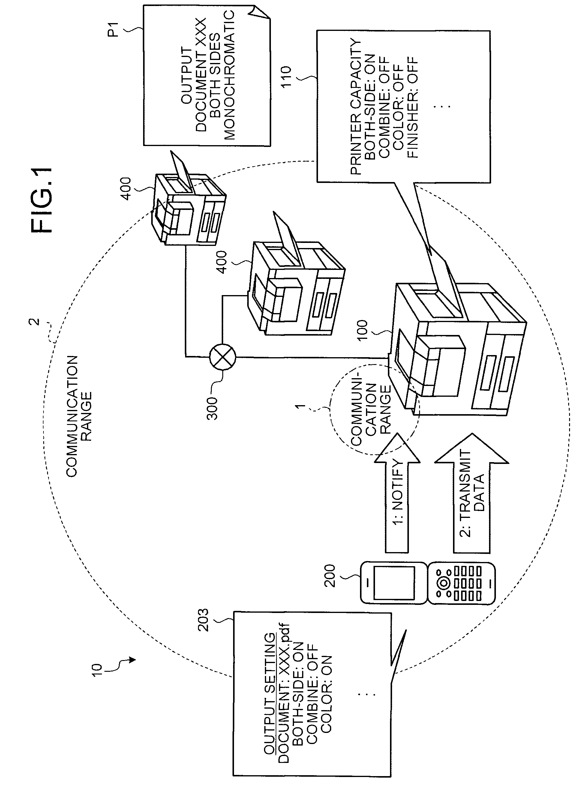
[0034]First, a configuration example of an information processing system including a multi function peripheral and a portable terminal device to which the present invention is applied is explained. FIG. 1 is a schematic diagram of a configuration of an information processing system 10 according to the The information processing system 10 includes a multifunction peripheral (MFP) 100, and a portable terminal device 200. The MFP 100 and the portable terminal device 200 can communicate with each other using two communication units as described later, within a communication range 1 indicated by a broken line and a communication range 2 indicated by a chain double-dashed line. The MFP 100 is connected to a network 300, and is also connected to another MFP 400, a facsimile device, and a client terminal device, via the network 300. In the portable terminal device 200, a user can set “both-side” printing to “on”, set “combine” to “off”, and set “color” printing to “on”, for data of documen...

second embodiment

[0123]In the first or second embodiment, after the function setting information stored in the portable terminal device is communicated with the MFP via the NFC unit, document data is automatically transmitted via the Bluetooth communication unit. The document data is printed following the function setting information transmitted in advance. However, depending on users, the function setting information set by the users is wrong, and unintended function setting information can be transmitted. In this case, an interval is necessary between the end of transmission of the function setting information and the start of transmitting the document data. Therefore, it is explained below a manual changeover between the obtaining of function setting information via the NFC unit (hereinafter, “function-information setting mode”) and the transmission of document data via the Bluetooth communication unit (hereinafter, “entity-information communication mode”).

[0124]FIG. 13 is a schematic diagram of ...

fifth embodiment

[0132]In the fifth embodiment, the function-information setting mode of obtaining the function setting information via the NFC unit and the entity-information communication mode of transmitting data such as document via the Bluetooth communication unit are manually changed over using the operation input unit at one position. However, users sometimes press the operation input unit by error, and change over between the function-information setting mode and the entity-information communication mode, by error. Therefore, a changeover between the function-information setting mode and the entity-information communication mode by providing the operation input unit at a different position in the MFP is explained below.

[0133]FIG. 15 is a schematic diagram of a configuration of an information processing system 60 according to a sixth embodiment of the present invention. The information processing system 60 includes an MFP 9000 and the portable terminal device 8000 (not shown). A configuration...


PUM


Abstract

A portable terminal device includes a first communication unit that transmits communication setting information and function information to an information processing device in non-contact communication, an input receiving unit that receives an input of the communication setting information and the function information, and a second communication unit that transmits entity information to the information processing device or receives entity information from the information processing device in non-contact communication.

Description

CROSS-REFERENCE TO RELATED APPLICATIONS[0001]The present application claims priority to and incorporates by reference the entire contents of Japanese priority document 2007-203573 filed in Japan on Aug. 3, 2007.BACKGROUND OF THE INVENTION[0002]1. Field of the Invention[0003]The present invention relates to an information processing system, an information processing device, and an information processing method.[0004]2. Description of the Related Art[0005]In recent years, with business machines such as a printing device, plural office devices are connected to a network, and a document can be printed by assigning a desired printing device from a client terminal such as a personal computer (PC) connected to the network.[0006]This configuration also applies to a multi function machine called a multi function peripheral (MFP) that includes a copy function, facsimile (FAX) function, printer function, and scanner function incorporated in one casing. The MFP can print documents by also assig...

Claims


Application Information

Patent Timeline
IPC IPC(8): H04B7/00
CPCG03G2215/00109H04M1/7253G03G15/5087G03G15/502H04W8/005H04M1/72412
Inventor OSHIMA, YUKIKOKATO, YOSHINAGA
Owner RICOH KK
Why Eureka
Try Eureka