Overlay transport virtualization

a technology of overlay transport and virtualization, applied in the field of overlay transport virtualization, can solve the problems of complex logical connection mesh, low network virtualization efficiency, and low network virtualization efficiency, and achieve the effect of improving network virtualization efficiency and reducing network virtualization costs

Active Publication Date: 2009-02-05
CISCO TECH INC
View PDF37 Cites 284 Cited by
  • Summary
  • Abstract
  • Description
  • Claims
  • Application Information

AI Technical Summary

Problems solved by technology

These conventional systems have a number of technical, operational, and cost drawbacks.
For example, all of these systems result in a complex mesh of logical connections.
Furthermore, this mesh usually creates forwarding and learning loops, which can only be broken by running Spanning Tree Protocol (STP) over the already complex logical mesh.
However, conventional methods for network virtualization do not work well in enterprise networks and typically lack the scalability and functionality for service provider networks.
Another drawback with conventional network virtualization is that the systems require multiple routing and forwarding tables to be maintained in every device in a path from a source node to a destination node.

Method used


Image

  • Overlay transport virtualization
  • Overlay transport virtualization
  • Overlay transport virtualization

Examples


example embodiments

[0024]The following description is presented to enable one of ordinary skill in the art to make and use the invention. Descriptions of specific embodiments and applications are provided only as examples, and various modifications will be readily apparent to those skilled in the art. The general principles described herein may be applied to other embodiments and applications without departing from the scope of the invention. Thus, the present invention is not to be limited to the embodiments shown, but is to be accorded the widest scope consistent with the principles and features described herein. For purpose of clarity, details relating to technical material that is known in the technical fields related to the invention have not been described in detail.

Overlay Transport Virtualization Overview

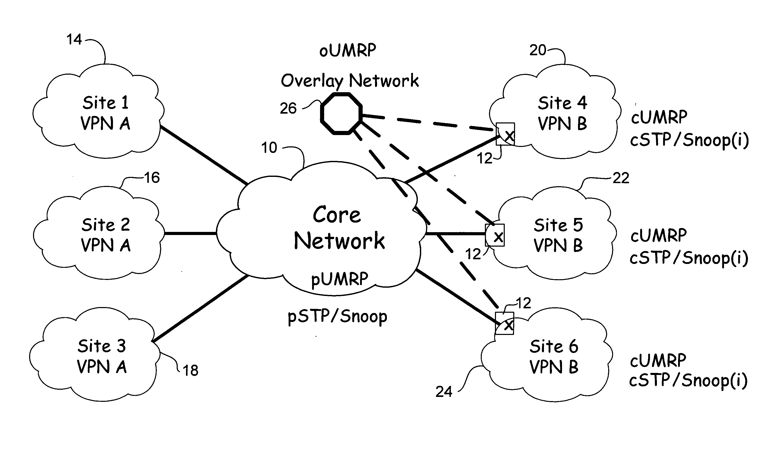
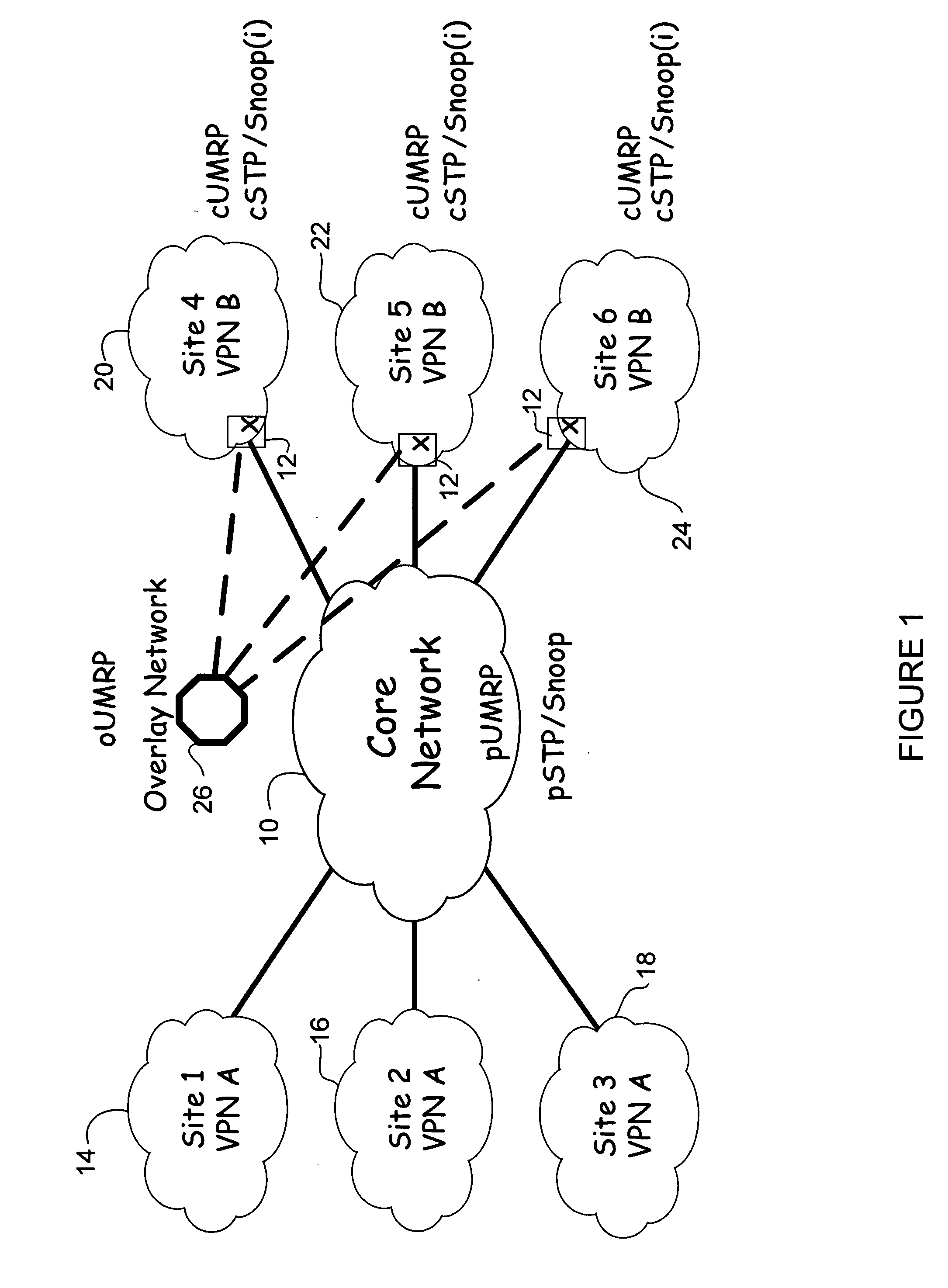
[0025]A method and system described herein support Layer 2 (L2) and Layer 3 (L3) virtual private networks (VPNs) over a L2 or Layer 3 (L3) infrastructure. The method and system are referred to...


PUM


Abstract

In one embodiment, an apparatus includes one or more internal interfaces in communication with one or more network devices in a first network site through a Layer 2 link, an overlay interface in communication through a Layer 3 link with a core network connected to one or more other network sites, and a table mapping addresses for network devices in the other network sites to addresses of edge devices in the same network site as the network device. The apparatus further includes a processor operable to encapsulate a packet received at one of the internal interfaces and destined for one of the network devices in the other network sites, with an IP header including a destination address of the edge device mapped to the destination network device, and forward the encapsulated packet to the core network.

Description

BACKGROUND OF THE INVENTION[0001]The present disclosure relates generally to supporting Layer 2 (L2) and Layer 3 (L3) virtual private networks (VPNs) over a Layer 2 or Layer 3 (L3) infrastructure.[0002]Many applications in a Data Center network require L2 connectivity between all servers running an application. In order to provide the required L2 connectivity across an IP transport, enterprises have had to either dedicate fiber interconnects to a L2 extension or use pseudowire based technologies such as EoMPLS (Ethernet over Multiprotocol Label Switching) or VPLS (Virtual Private LAN Service). Others have opted for low performance IP based point-to-point solutions such as L2TPv3 (Layer 2 Tunneling Protocol Version 3) on software switched platforms. These conventional systems have a number of technical, operational, and cost drawbacks. For example, all of these systems result in a complex mesh of logical connections. Furthermore, this mesh usually creates forwarding and learning loop...

Claims


Application Information

Patent Timeline
Patent Type & Authority Applications(United States)
IPC IPC(8): G06F15/16
CPCH04L12/4641H04L29/12028H04L61/6022H04L61/103H04L61/106H04L29/12839H04L12/1886H04L2101/622
Inventor FARINACCI, DINOSPEAKMAN, TONYVENUGOPAL, NAIRGROVER, HASMITMORENO, VICTORRAO, DHANANJAYA
Owner CISCO TECH INC
Why Eureka
Try Eureka