Platen assembly

a platen and assembly technology, applied in the field of platen assembly, can solve the problems of poor print quality or other problems, platen rollers may need to be replaced, and the alignment between the printhead and the platen is disturbed, so as to achieve convenient replacement and easy alignment. the effect of user

Active Publication Date: 2009-02-12
ZEBRA TECH CORP
View PDF2 Cites 24 Cited by
  • Summary
  • Abstract
  • Description
  • Claims
  • Application Information

AI Technical Summary

Benefits of technology

[0012]The present invention addresses the above needs and achieves other advantages by providing a platen assembly comprised of a platen roller assembly and a housing assembly that is structured to rotatably support the platen roller assembly. More particularly, the present invention is directed to a platen roller assembly comprising a platen roller defining first and second ends; a locking pin or other drive element extending from at least one of the first and second ends of the platen roller; a housing assembly adapted to rotatably support the platen roller; and a drive assembly structured to rotatably engage the locking pin extending from one end of the platen roller. In this regard, the present invention provides a platen roller assembly that is simple, easily alignable, and readily replaceable by a user without requiring the use of tools or disassembly of the drive assembly.

Problems solved by technology

Over the lifetime of a printer, platen rollers may need to be replaced due to abuse or normal wear and tear.
If not replaced, a worn out or otherwise defective platen roller may provide uneven pressure against the printhead causing poor print quality or other problems.
However, each time the platen is exchanged, the alignment between the printhead and platen is disturbed.
As will be apparent to one of skill in the art, it is typically quite difficult to manipulate screwdrivers or other tools within the tight confines of the printer housing.
It also may be difficult to disassemble the drive assembly (e.g., stepping motor, drive belt, etc.).

Method used


Image

  • Platen assembly
  • Platen assembly
  • Platen assembly

Examples


Embodiment Construction

[0028]The present invention now will be described more fully hereinafter with reference to the accompanying drawings, in which some, but not all embodiments of the invention are shown. Indeed, the present invention may be embodied in many different forms and should not be construed as limited to the embodiments set forth herein; rather, these embodiments are provided so that this disclosure will satisfy applicable legal requirements. Like numbers refer to like elements throughout.

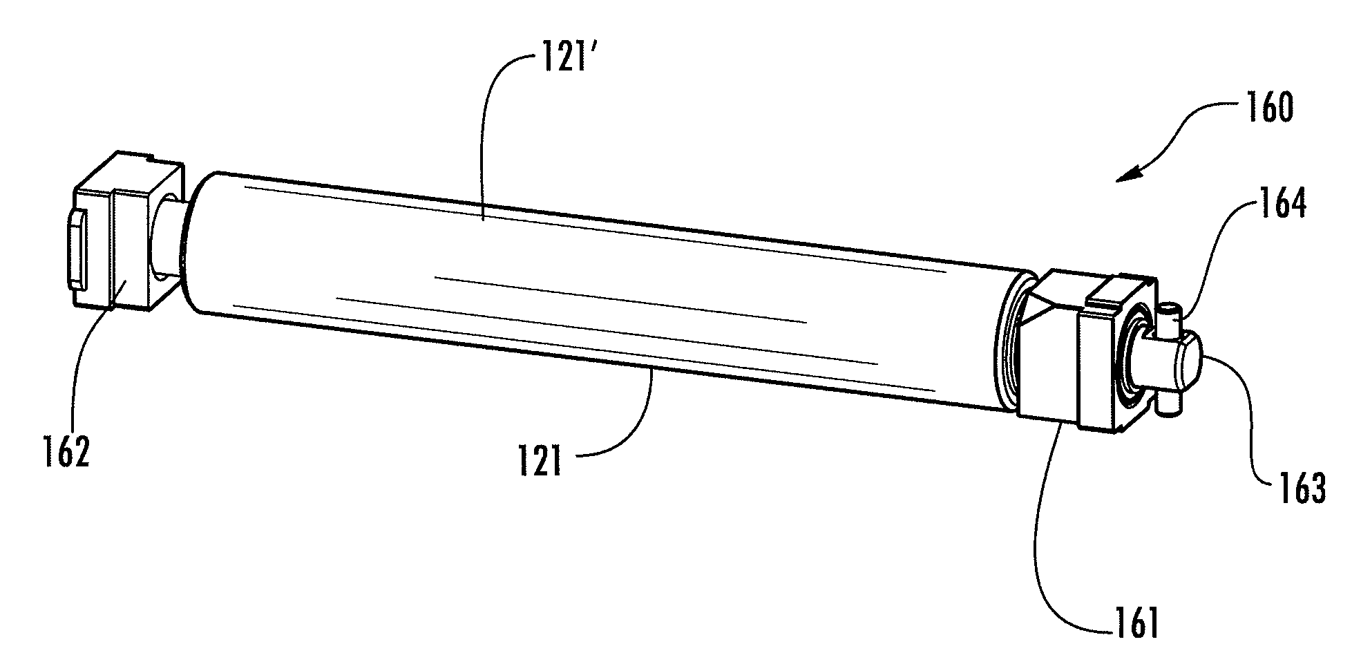
[0029]FIG. 4 depicts a printer 100 structured in accordance with one embodiment of the present invention. The depicted printer 100 comprises a printer housing 114 enclosing various internal printer components. Such internal printer components may be comprised a media support assembly 113, a printhead assembly 140, and a platen assembly 120. The media support assembly 113 may be a hanger, as shown, for supporting a spooled media such as adhesively backed labels. As is readily apparent to one of ordinary skil...


PUM


Abstract

A platen assembly for a printer comprised of a platen roller assembly and a housing assembly that is structured to rotatably support the platen roller assembly. More particularly, the present invention is directed to a platen roller assembly comprising a platen roller defining first and second ends; a locking pin extending from at least one of the first and second ends of the platen roller; a housing assembly adapted to rotatably support the platen roller; and a drive assembly structured to rotatably engage the locking pin extending from one end of the platen roller. In this regard, the present invention provides a platen roller assembly that is simple, easily alignable, and readily replaceable by a user.

Description

BACKGROUND OF THE INVENTION[0001]1) Field of the Invention[0002]Various embodiments of the present invention relate generally to an improved platen assembly for a printer and, more specifically, to a platen assembly that is structured for quick and efficient installation, removal, and / or replacement.[0003]2) Description of Related Art[0004]Platen rollers are widely used in printers to drive media against a printhead during printing operations. The platen roller provides a soft, often rubberized, surface for gripping and manipulating the media against the printhead. For print quality purposes, it is often important for the platen roller to apply a relatively constant and uniform pressure against the printhead along the full length of the platen roller.[0005]Over the lifetime of a printer, platen rollers may need to be replaced due to abuse or normal wear and tear. If not replaced, a worn out or otherwise defective platen roller may provide uneven pressure against the printhead causin...

Claims


Application Information

Patent Timeline
Patent Type & Authority Applications(United States)
IPC IPC(8): B30B15/06
CPCB41J11/04
Inventor BUTZEN, JAMES K.MYRE, JAKEURBAN, MARK
Owner ZEBRA TECH CORP
Why Eureka
Try Eureka